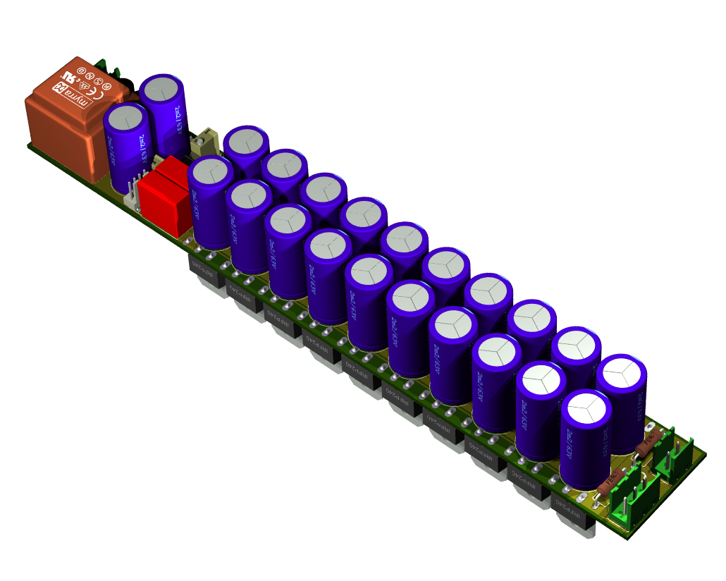
often pcb designers have a fiction or a vice with symmetrics and size ( including me ) ....playing this game might end up with an ultra compact and symmetric pcb but that comes with a a couple of troubles
one : that no one can use a bigger semi for the output if exist or if needed
two: keeping so many output semis so close to each other means that the heatsink has to be made of zorex, kryptonex, starson or any other material from the moon or jupiter to be able to absorve this type of heat ...
one : that no one can use a bigger semi for the output if exist or if needed
two: keeping so many output semis so close to each other means that the heatsink has to be made of zorex, kryptonex, starson or any other material from the moon or jupiter to be able to absorve this type of heat ...
Federmann
Has anyone ever built this layout and effectively cooled it?
I am strugging to envisage an efficient heatsink layout to suit.
Maybe a re-design is required to the layout of the output mosfets to suit the real world.
For a working example, look at Quasi's designs which are documented on his website
Quasi's DIY Audio Site
10 pair of IRFP mosfets driven by the VAS directly?!
Not even 2 pairs should be driven directly from the vas
")
Not even 2 pairs should be driven directly from the vas
There is no reason to give more of the transistor.
Not even 2 pairs should be driven directly from the vas
It depends on how much current goes through the VAS.
I have succesfully used 3 pairs with just a VAS driver, the frequency response was fine over the audio range.
Federmann
Has anyone ever built this layout and effectively cooled it?
I am strugging to envisage an efficient heatsink layout to suit.
Maybe a re-design is required to the layout of the output mosfets to suit the real world.
For a working example, look at Quasi's designs which are documented on his website
Quasi's DIY Audio Site
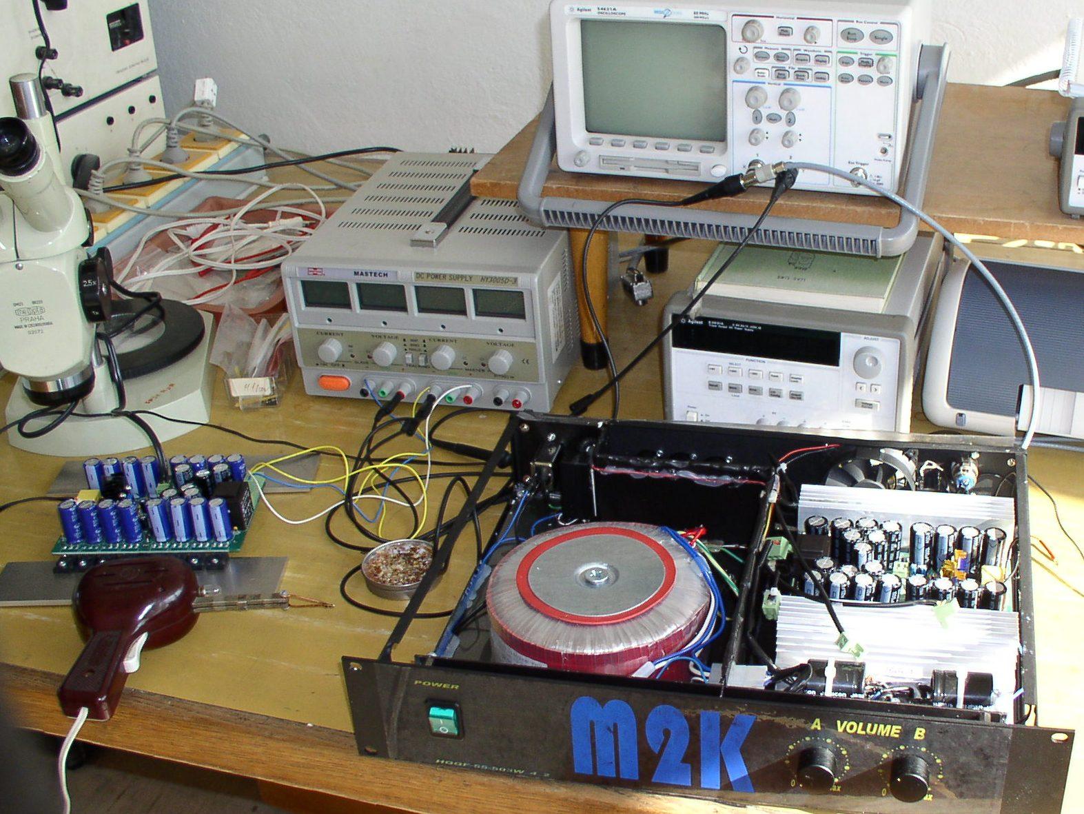
8 pairs and 2x500W
the heatsink has to be made of zorex, kryptonex, starson or any other material from the moon or jupiter to be able to absorve this type of heat ...
What about liquid nitrogen !?
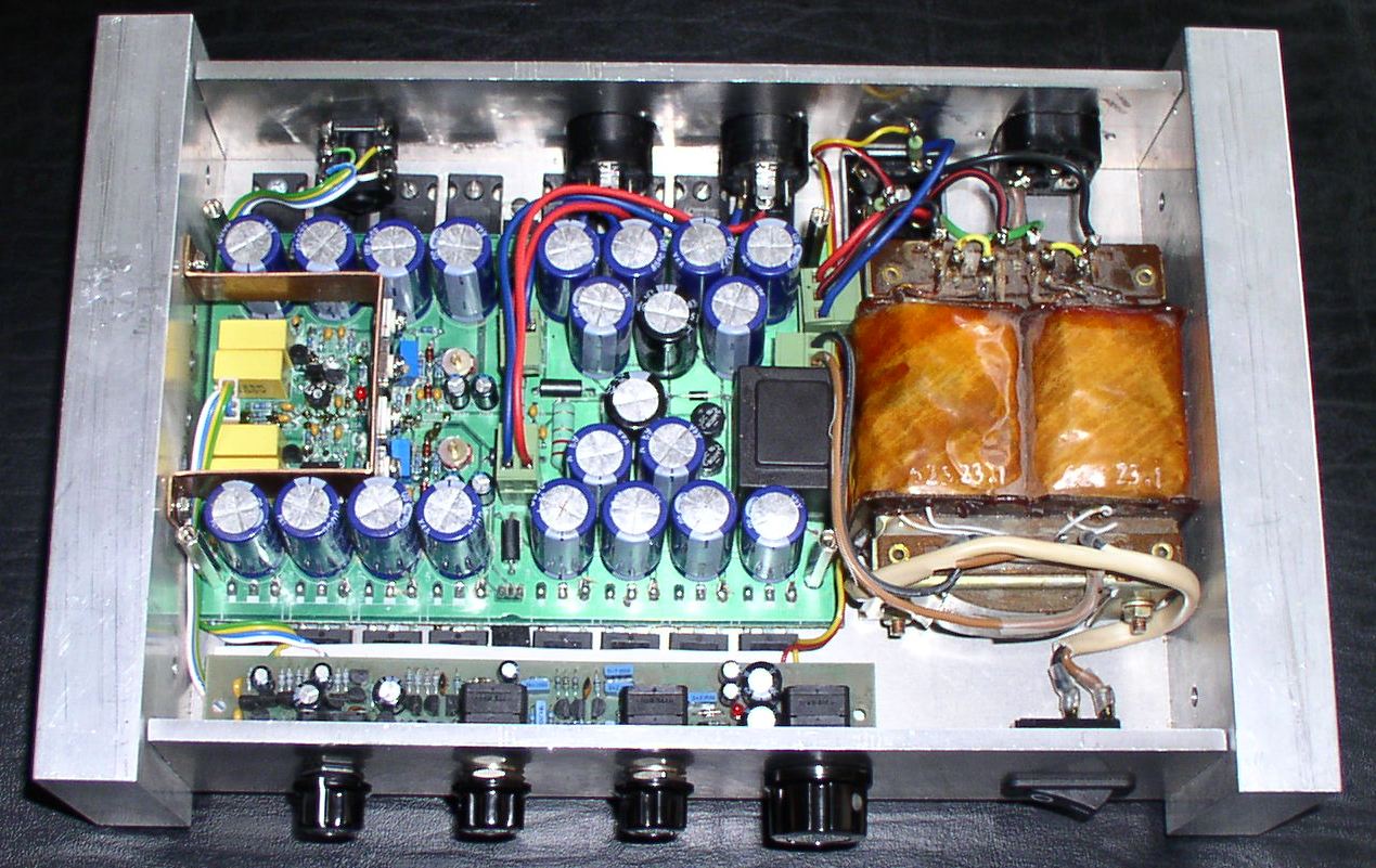
I see now that the FETs are angled outwards 'in the real world'!
The new layout shows the temperature compensation transistor for the bias, not central to the heatsink, is this not an issue?
Also I would like to add my vote to the addition of a proper driver stage after the VAS. With FET amps I have modified to include a driver stage, I have noted better stability when driving real loads.
Why is the capacitor C15, that is connected across the Feedback Resistor R17 trimmable?
Apart from that I like the distributed resevior capacitance on the output stage, & the separate PSU for the Driver Stage.
I see now that the FETs are angled outwards 'in the real world'!
Second possibility FEFs may be Al prism 30x20mm, then the cooler.
Federmann,
The symbols you used in the schematic of your amplifier for P-channel Fets is Wrong.....
Correct it.
I like the simplicity of your amplifier, at what current your VAS is running, since your driving a bunch of 10 Fet pairs directly.
Kanwar
I do not have the EAGLE TO247AC for P.
Current T6-T7 = 10 ÷ 15 mA/pair, 10 pairs of 100-150 mA.
I do not have the EAGLE TO247AC for P.
Current T6-T7 = 10 ÷ 15 mA/pair, 10 pairs of 100-150 mA.
Strange to know that you dont have symbol for P-channel in eagle for schematics.
Running VAS at 100-150mA means differential pair transistors must be running at around 10-15mA
10 pair of IRFP mosfets driven by the VAS directly?!
well, it s doable if one is satisfied with a THD ratio that
is ten fold higher than when adding an EF buffer stage....
well, it s doable if one is satisfied with a THD ratio that
is ten fold higher than when adding an EF buffer stage....
Please do not measure THD at 1kHz, measure, please THD at 100kHz. Many transistors does a very slow amplifier.
- Status
- This old topic is closed. If you want to reopen this topic, contact a moderator using the "Report Post" button.
- Home
- Amplifiers
- Solid State
- amp 1000W/2000W, IRFP240/9240