Following, I overhauled my ex Canadian Navy 3501A about 8 yrs ago after a relay failed and one of those tantalum drop capacitors caught on fire.
I replaced them with aluminum electrolytics (low impedance type) and noted a very slight increase in measured thd in loop back testing at 1kHz.
Tonight in loop back at 1Vrms out I was able to get no better than 0.0013% at 1kHz with 30kHz LPF.
I've owned this unit since 1999 (spring/summer?). I guess maybe I need to look at some improvements when I have time. Perhaps start by replacing those electrolytics I mentioned with Oscons or similar..
I used 35V tantalums to replace the original 25V tantalums in the hopes that increased noise wouldn't be a problem. I'm testing mine at about 1.2V out on the 0dB output range as distortion drops a bit with the output cranked to the top of the respective range. I do the same thing with my 339A oscillator running it maxed at slightly above 1V on the 1V range.
U2008 and U1030 will make the most difference since they have significant common mode. Those may benefit from AD797's which work well in common mode. And they are relatively easy to get to. The noise is an issue. Running the internals at 300mV makes noise a bigger issue. I looked at the input monitor and its pretty clean. The harmonics can all be below -110dB. I think I have a plan now. And I won't need 20 LME49710's.
I'll need to check the supply rails for noise however that's not likely to be a big issue from what I see for now.
I'll need to check the supply rails for noise however that's not likely to be a big issue from what I see for now.
On the Boonton the AD797 had the lowest distortion in the summing for the differential input. I tried a numbe of opamps. it was noisier at the input follower (input current noise).
What has be concerned is that with the original parts as shipped these should be good for .0006% THD+N. usually ist not semiconductors that degrade over time. The circuit paths are simple and few caps to be problems. Its possible a semi junction was damaged but usually those are obvious. The distortion is not coming from the input circuit since its not present enough at the monitor. Some aspect of the analyzer/oscillator PCB has degraded enough to be an issue. Both the oscillator and the analyzer are not up to original specs. I hope its not the tuning pot. Any other ideas? Whatever this highlights may be relevant to the 5500 which has similar symptoms.
What has be concerned is that with the original parts as shipped these should be good for .0006% THD+N. usually ist not semiconductors that degrade over time. The circuit paths are simple and few caps to be problems. Its possible a semi junction was damaged but usually those are obvious. The distortion is not coming from the input circuit since its not present enough at the monitor. Some aspect of the analyzer/oscillator PCB has degraded enough to be an issue. Both the oscillator and the analyzer are not up to original specs. I hope its not the tuning pot. Any other ideas? Whatever this highlights may be relevant to the 5500 which has similar symptoms.
Still following, looking forward to hearing what makes the most difference for the least cost and effort. I just don't want to invest a lot of time or money in this instrument since what I use it for doesn't warrant performance better than what it exhibits. (tube guy here) I also have an RTX coming at some point late summer and early fall which is where I pin all of my hopes..
I'm on the same page. Step one get to the factory performance. Step two a few modt to get a little better or more stable.
The RTX6001 has some performance thats way better but in some areas a well tuned analog analyzer is hard to beat. The combination becomes really powerful.
The RTX6001 has some performance thats way better but in some areas a well tuned analog analyzer is hard to beat. The combination becomes really powerful.
I had time this morning to install the Luna NSL-32 optocoupler and test it. Long story short, I reinstalled the CLM-8500.
Before installing the Luna I tested the 3501 analyzer with both the 3501 osc in loopback and the 339A oscillator. Before starting I went back in and set up the 2H cals for the 3501 oscillator using the QA400, this helped a lot. I had set this up a few months ago and it was < .0006% after I set it up back then. I knew that it had drifted some over the past months, today it was sitting at .00078%. After tuning the oscillator I was able to get the 3501A readings to .00058% in loopback. I then setup the notch filter again and now I'm getting down to .00051% (+/- .00001%) in loopback on the 3501. The 339A osc when measured on the 3501 analyzer actually degraded just a bit after I optimized the notch for the 3501 oscillator. The 339A oscillator is now measuring about .0004%. These readings are all at 1kHz, with the 400HP and 30kHz LP filters active and the 3501 osc level pot on the 0dB setting and the volume pot maxed out (1.2V out).
So after all the tweaking and tuning I installed the new Luna optocoupler. The best I could achieve with the Luna in place was .0008% when measuring the 3501 osc. The 339A osc only measured slightly better at .0007% with the luna optocoupler. I tried retuning the notch again but nothing would bring the distortion readings down to their original levels. After reinstalling the CLM8500 I was able to tune the measurements right back to their original levels.
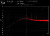
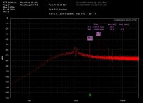
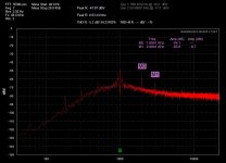
I've included a few screen grabs of the QA400 showing the 3501 distortion residual. The first is the 3501 osc before I retuned it, the second pic is after retuning the 2H and notch. I'm able to get the 3501 oscillator's 2H down to < -50dB when tuning but within 10 min or so it drifts back up 3 - 4 dB to the level shown in the after tuning picture. For comparison I also included a picture of the 339A oscillator. You can see that the 3H is still a big problem with the 3501 oscillator.
Before installing the Luna I tested the 3501 analyzer with both the 3501 osc in loopback and the 339A oscillator. Before starting I went back in and set up the 2H cals for the 3501 oscillator using the QA400, this helped a lot. I had set this up a few months ago and it was < .0006% after I set it up back then. I knew that it had drifted some over the past months, today it was sitting at .00078%. After tuning the oscillator I was able to get the 3501A readings to .00058% in loopback. I then setup the notch filter again and now I'm getting down to .00051% (+/- .00001%) in loopback on the 3501. The 339A osc when measured on the 3501 analyzer actually degraded just a bit after I optimized the notch for the 3501 oscillator. The 339A oscillator is now measuring about .0004%. These readings are all at 1kHz, with the 400HP and 30kHz LP filters active and the 3501 osc level pot on the 0dB setting and the volume pot maxed out (1.2V out).
So after all the tweaking and tuning I installed the new Luna optocoupler. The best I could achieve with the Luna in place was .0008% when measuring the 3501 osc. The 339A osc only measured slightly better at .0007% with the luna optocoupler. I tried retuning the notch again but nothing would bring the distortion readings down to their original levels. After reinstalling the CLM8500 I was able to tune the measurements right back to their original levels.
I've included a few screen grabs of the QA400 showing the 3501 distortion residual. The first is the 3501 osc before I retuned it, the second pic is after retuning the 2H and notch. I'm able to get the 3501 oscillator's 2H down to < -50dB when tuning but within 10 min or so it drifts back up 3 - 4 dB to the level shown in the after tuning picture. For comparison I also included a picture of the 339A oscillator. You can see that the 3H is still a big problem with the 3501 oscillator.
Attachments
That's an interesting and apparently unexpected outcome.
Definitely unexpected, If anything I had expected no change with the Luna in place of the Clairex part.
I need to look at replacing the single turn adjustment pots in the Notch and Oscillator sections. They are so touchy if you just look at them wrong they drift.
Let me touch on why swapping parts can be frustrating. There are several aspects to the optocouplers. The Clarex has an on resistance of around 500+ Ohms and an off resistance around 1 Meg. The Luna NSL-32 is much lower on and higher off. The NSL-28 is a closer match. The important question when its operating is what the current in the LED is and what the voltage across the photocell is (and indirectly what the resistance of the photocell is). Ideally the voltage across the cell should be very low, like 10 mV but that may not work with the other aspects of the circuit. Its not hard to find yourself out of the optimum operating range of the system. Same with the opamps connected to the input Jfets etc.
In the 3501 the cell is used for the level loop in the notch filter. The frequency tuning is done with a pair of OTA's. Those are odd beasts that are not used often today. They seem to work quite well in this application when everything is right. What I may do next is try to feed the notch filter directly from an LDO to see if the issues can be located and addressed.
The 5500 has 4 optocouplers so I'll be looking at them carefully.
Its possible that drift in the caps could be degrading the null but not the harmonic distortion performance. That is a different problem.
I have been working on software to control the Boonton 1120/Keithley 2015/Amber 5500/HP8903. Its progressing with various fits and starts. Hopefully when done it will be useful. Its taking some time from other projects like fixing the Amber.
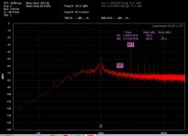
I spent some more time today investigating the 3501 tuning in more depth. What I found is that part of the problem is that reinstalling the upper cover after tuning causes the oscillator's 2nd harmonic to jump up by about +10dB or more in my 3501. I believe this was part of the tuning drift that I was seeing. What I had to do to get around this is to lift the cover and slide it to the left just far enough to be able to access the osc 2H trim pots V2009/V2010. Doing this leaves the cover in close proximity to the upper board and minimizes the shift in 2H when the cover is put in place.
Doing the adjustment in this manner yielded a much better tuning of the 2H. See the attached picture. Compare this picture to the middle pic in post #30.
The other problem I have is heat related. The 2H drifts by about +10 - 15dB within about 10 min or so after the upper cover is reinstalled. If I remove the upper cover and let the heat dissipate for a few minutes and then reinstall the cover the 2H is right back where it was after the tuning. The largest amount of heat inside of my 3501 is coming from the transformer which was moved in the later production units inside of the main box. I will have to investigate either cutting a hole in the rear panel and installing a 50mm cooling fan or moving the transformer to an external enclosure. You folks with the early prod models with an external transformer housing are lucky in this regard. I;m thinking an ext transformer enclosure is probably the route I need to go.
Attachments
Last edited:
I have one with an external transformer. When i gopt it the transformer was not part of the package. I found a suitable external transformer from Jameco along with a matching connector and replaced the one on the back. That worked fine. its still running warm.
I'm focusing what little time I have right now on an app to run the analyzers that have GPIB type of control. Its much more involved than I thought to get everything working. Not usable with a 3501 but I'll try to make it work with the 5500 soon. Unfortunately no time or space to work on hardware right now.
I'm focusing what little time I have right now on an app to run the analyzers that have GPIB type of control. Its much more involved than I thought to get everything working. Not usable with a 3501 but I'll try to make it work with the 5500 soon. Unfortunately no time or space to work on hardware right now.
Anyone that might be interested in acquiring an old Amber 3501 not the "a" version. There is an equipment seller on the bay right now with multiple units listed. They're in as-is untested condition, but the seller is accepting offers and I can attest that he is accepting lower offers. I picked one up yesterday to have a spare parts unit. For the price if you get a working unit or even if it needs a little TLC, which is very likely but the manual is avail online, you'd be hard pressed to find a better deal on an old analog analyzer with the performance you can get out of these. They make a nice front end for your soundcard too.
FYI I'm not affiliated in any way with the seller.
FYI I'm not affiliated in any way with the seller.
Well I botched that. As usual I got it backwards, they are the "a" version.
Anyone that might be interested in acquiring an old Amber 3501 not the "a" version. There is an equipment seller on the bay right now with multiple units listed. They're in as-is untested condition, but the seller is accepting offers and I can attest that he is accepting lower offers. I picked one up yesterday to have a spare parts unit. For the price if you get a working unit or even if it needs a little TLC, which is very likely but the manual is avail online, you'd be hard pressed to find a better deal on an old analog analyzer with the performance you can get out of these. They make a nice front end for your soundcard too.
FYI I'm not affiliated in any way with the seller.
Very interesting thread, glad to hear others using and working on them. I have a couple of them, non-A versions, both older versions with ext transformers.
I have a printed manual, which is earlier than the later one found on the net.
Same here,I've got three non-A's,all with the frequency counter.
I actually have the complete Transport Canada Aviation Services printed manual for these,but it's in French,haha!
Is your manual for an earlier non-A model?
- Home
- Design & Build
- Equipment & Tools
- Amber 3501A Dist. & Audio Analyzer Needs Refurb and Cal.