It's a bit tricky cos the clocks are interlinked, so you can't be sure which is outputting I guess as they're both on the same track, but a good safe point to start with is to measure at R1 or R2 and make sure a 1.6vish clock signal's coming out of the buffer when playing music of both 44k and 48k frequency families.James, at what point on the board would you suggest, I should take the measurement?
Thanks,
Assuming that's ok, I guess you check if the clock select is working. Maybe you can override it and lock it manually in each position while you test. I don't know, I'm very new to this all too.....
Already tried as it happens")
I believe the original 192k spec of the DDDAC 1794 was due to the limit of the original WaveIO, but once the updated xmos firmware was released for that, 384k was no problem. Using a wandboard running csos with upsampling using sox and the WaveIO, I can output at 384k and the DDDAC plays it with no issue
Interesting, but nothing in the spec sheet for PCM1794 indicates this capability, afaik (Fs up to 200k only). Maybe some hot-rod version of this chip that I am not aware of?
Anyway, have you tried playing some native HiRes files from 2L on your WaveIO-DDDAC?
http://www.lindberg.no/hires/test/2L38_01_DXD.zip (DxD 352.8k pcm 24bit)
I have trouble getting Amanero to play this on my 9018 system. Maybe Botic-BBB would do better?
Last edited:
It's a small disappointment for me. The prefix SUPER made me think it would be more complete, with all signals insulated, reclock, appropriate power supply for oscillators, maybe RJ45 connectors and / or HDMI to connect Dac as PS Audio, ......
It might be a good idea to open a new thread for a MEGA CAPE and see if there is interest in something really "complete".
Regards
We will get there, all in good time, but first we need to see if the SQ and other features are worth the efforts - results are only just trickling in. BTW, this is a not a commercial project. More of a crowd supported development for DIY.
No project creep but BBB needs to be in a well formed interface for audio before it can be used conveniently, so all the current efforts that seemingly looks like something totally different.
As you can see there are other transports that also lines up pretty well. Someone has even asked how to get WaveIO and even SDTrans384 into a synchronous re-clocking mode with S03 - more on these later!
No special version, but the DDDAC runs it with all filters disabled in a way which isn't in the datasheet.Interesting, but nothing in the spec sheet for PCM1794 indicates this capability, afaik (Fs up to 200k only). Maybe some hot-rod version of this chip that I am not aware of?
I'll try and double check with that file when I can find a minute to dig out the WaveIO.
Is it possible I was successfully feeding 384k to the WaveIO, but that it was only giving 192k to the DDDAC?
It's a bit tricky cos the clocks are interlinked.......
Thanks, I was planning on upgrading the clocks anyway this weekend so I'll test with just X2 in place and see if I get 1.6V at clocks output CK.
I still also don't understand why my clock selection is inversed and what could be causing this.
No special version, but the DDDAC runs it with all filters disabled in a way which isn't in the datasheet.
I'll try and double check with that file when I can find a minute to dig out the WaveIO.
Is it possible I was successfully feeding 384k to the WaveIO, but that it was only giving 192k to the DDDAC?
Pretty sure I tested DSD128 L2 test files and it played fine on the DDDAC with the new firmware on the WaveIO.
Lorien wrote:
H. Now you have 24 bit PCM / 32 bit PCM / DoP64 / DoP128 / DSD46 / DSD128 - all enabled.
http://www.diyaudio.com/forums/digital-source/188902-xmos-based-asynchronous-usb-i2s-interface-212.html#post4016871
.... Thought CKSEL line is low for 44.1k and goes high for 48k- based frequencies. Please check the lines again for both settings.
Hi Acko,
With the inverted polarity in Miero's driver, when CKSEL is high X1 seems to be selected and 44.1kHz plays fine, when 48kHz file is played (CKSEL is low) mpd plays but I get no sound.
With the standard Miero driver value of 3 for a botic, mpd crashes on 44.1K (CKSEL is low), with 48kHz file plays but to slow.. (CKSEL is high)
In "all" 4 cases I have 1.6 volt at CK.
I've swapped the clocks out but same symptoms as before, so I suspect it's logic before the clocks, either U8 or Q2. What do you think?
One more thing, I noticed that when I touched earthtraces with a probe, sometimes the clock seemed to jump from x1 to x2, very strange.
Last edited:
.....In "all" 4 cases I have 1.6 volt at CK.
I am trying to figure out your problems. We know both Chanh's and Cyrils's build worked well with "option #3"
Can you please check the the Clock signal that is actually going into BBB, ie. the output at MCK of "Digital Inputs"
Acko: I would like to use touchscreen for the BBB, but all ones i seem to find does have its own cape... i guess it would make it impossible to use both your cape and those at the same time...?
I believe, the Botic audio signals will conflict with the designated lcd ones on BBB. If local display is somehow possible you will still need to create software for the graphical interface. In any case the plan is for a deeply embedded device with remote display using some web-based stuff. Hopefully RuneAudio, etc will do that
An externally hosted image should be here but it was not working when we last tested it.
Hmmm... Can you please cut the black wire coming out from your CKSEL of the BBB-UFL board. You will only need a single (the "white") wire to S03 "sel" point on board as shown in the manual
Next check if this line/point (at the BBB-UFL board pin#24) switches correctly for different Fs. Expecting with Botic option#3, to go high (3.3V) when 48k file played and low when 44.1k played
Last edited:
Hi Acko,
Just arrived....
You have any idea about the manufacturer for the FFC/FLC connectors?
Thanks and Regards,
Enrico
Fantastic!
You may try these matching connectors:
PN: 1112559 Farnell
Flat cable PN: 732-3567-ND Digikey
An externally hosted image should be here but it was not working when we last tested it.
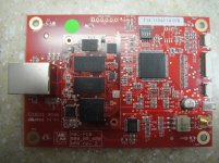
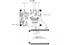
Suspect: U8 input side may not be powered? Your header does not seem to pick one of the 3.3V pads. Both 3.3V pads need to be connected (or bridged). See wiring diagram.
Possible CKSEL signal when "HIGH" is weakly powering up the isolator with undesirable effects.
Attachments
Fantastic!
You may try these matching connectors:
PN: 1112559 Farnell
Flat cable PN: 732-3567-ND Digikey
Many thanks acko, they are the ones
All the Best,
Enrico
Suspect: U8 input side may not be powered? Your header does not seem to pick one of the 3.3V pads. Both 3.3V pads need to be connected (or bridged). See wiring diagram.
Possible CKSEL signal when "HIGH" is weakly powering up the isolator with undesirable effects.
That explains the “monkey” behaviour. It never occured to me to jumper these pins, as most other builds I had close-ups of only used a single clock, they didn’t needed to power both pins.
Thanks a lot Acko for taking the time to investigate this issue
Everything is working fine now using Miero’s setting “3”.
I also upgraded to these NDK NZ2520SD’s, they are tiny! I'm really starting to enjoy this miniature soldering.
An externally hosted image should be here but it was not working when we last tested it.
Last edited:
- Status
- This old topic is closed. If you want to reopen this topic, contact a moderator using the "Report Post" button.
- Home
- Group Buys
- Amanero Isolator/Reclocker GB