Nice work Hermann
Because the oscillator is only driving the flipfops in this configuration and you're not using mck output from the S03, the buffer isn't really needed I don't think? Maybe you can try the same with disconnecting the power for the buffer chip and bridging the input pin to output pin so the oscillator directly drives the flipflops and see if anything is different?
I have my S03 with DDDAC set up like this and it works fine. I figure less complication is always a good thing, but I'd be interested to see whether you can measure any difference between using the buffer and going direct from oscillator to flipfops.
regards,
James
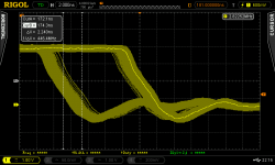
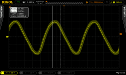
Thanks for the idea, I just tried it, but the results did not change. Here you see the waveform / jitter of the I2S signal before the FF where there's a 2ns jitter but with no jitter "in-between":
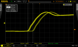
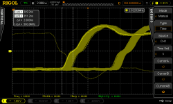
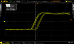
And here's the waveform after the FF, whereas the 10ns jitter can be easily seen but also with a jitter of approx. 2ns whereas I bridged + disabled the buffer as you recommended:
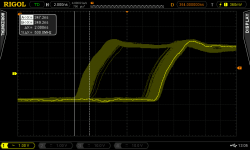
And here's the same with the buffer:
I personally can't see any real difference between the two waveforms (except that one is triggered on the rising edge, the other on the falling, but that makes no difference).
What may be interesing is that it seems that it is a "minority" of signals that build up this 2ns jitter, so it seems (have no idea how to measure it, unfortunately), that statistically, maybe 80-90% of the signal has a far lower jitter than 2ns.
I moreover tried another thing: I tried reclocking a signal with the S03 of my waveform generator, especially a signal of 1 MHz, just to see what asynchronous reclocking does to a signal that is a denominator of the original signal (e.g. 1MHz = 1/100 of 100Mhz).
In this case the 10ns jitter still randomly occurs, but a lot less often than for signals where the clock is no denominator of the clock the signal is reclocked to. It can be nicely seen that if I set the signal from 1 to 1.1MHz, the jitter occurs a lot more frequent than when setting it to 1Mhz.
Thus I think that using a clock for reclocking in an asynchronous manner, using a multiple of the original signal will be better.
Unfortunately, the 2ns jitter of the output signal after the FF was still there. I personally hoped that this 2ns jitter was some side-effect of the distinct 2ns-jitter at the input of the FF but it was not.
Best Regards,
Hermann
Attachments
More great investigations Hermann ") at least it proves that in this case the buffer isn't needed, so we can reduce the complexity, component count and power supply requirement with no negative effects.
at least it proves that in this case the buffer isn't needed, so we can reduce the complexity, component count and power supply requirement with no negative effects.
Using an oscillator that's a multiple of the most popular frequency makes a lot of sense if they're available? I know 95% of my music is red book 44.1khz, so something set up for that would be sensible
at least it proves that in this case the buffer isn't needed, so we can reduce the complexity, component count and power supply requirement with no negative effects. Using an oscillator that's a multiple of the most popular frequency makes a lot of sense if they're available? I know 95% of my music is red book 44.1khz, so something set up for that would be sensible
Hello Acko,
I am about to buy your S03 board for my project: BBB + BuffaloIIISE Dac -> fully async.
As far as I understand, I could get the 98/90 dual master version according to the schematics you have already published. Do please correct me if I got it wrong.
I have just one question: which clock versions are included in the kit ? (I would love to get some good stuff like the Crysteks or NDK, are they available ?)
best regards
Pepe
Hello Acko,
I am about to buy your S03 board for my project: BBB + BuffaloIIISE Dac -> fully async.
As far as I understand, I could get the 98/90 dual master version according to the schematics you have already published. Do please correct me if I got it wrong.
I have just one question: which clock versions are included in the kit ? (I would love to get some good stuff like the Crysteks or NDK, are they available ?)
best regards
Pepe
S03 can drive the BIII in ASync mode. Just use the on-board 100MHz Clock of the BIII for the 9018 MCK and you will need the 100M (98.xx/90.xx) version of S03 - currently available and uses NDK2520 type.
Happy New Year to All! I am back on deck and lots of catching up to do. I will respond to your posts and messages soon. There are a few new toys to show as well
Hi Acko,
Well come back and Happy New year to you!
You talk about new toys
... I am waiting for the delivery of the NMR_OEM board Regards,
Enrico
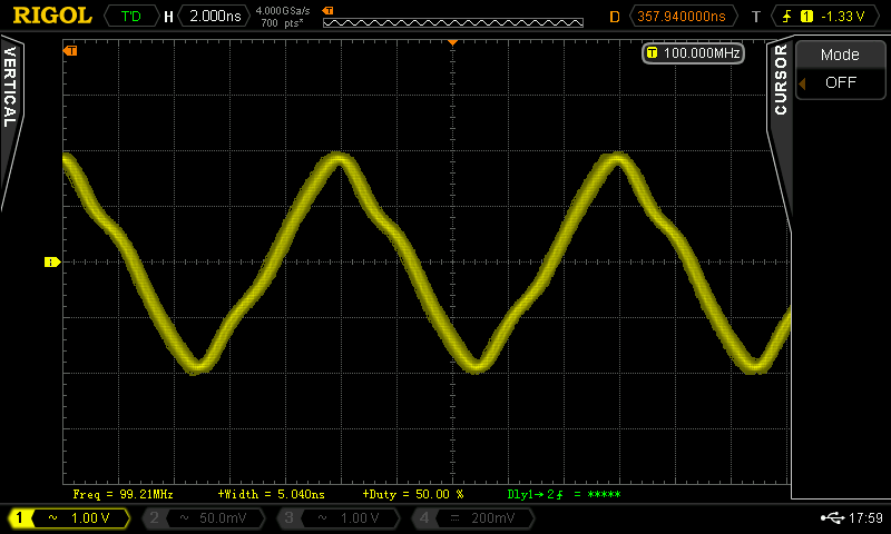
A look at the 100MHz input of the D-FF shows that the signal is clean but not rectangular, which maybe could be an explanation to the jitter?
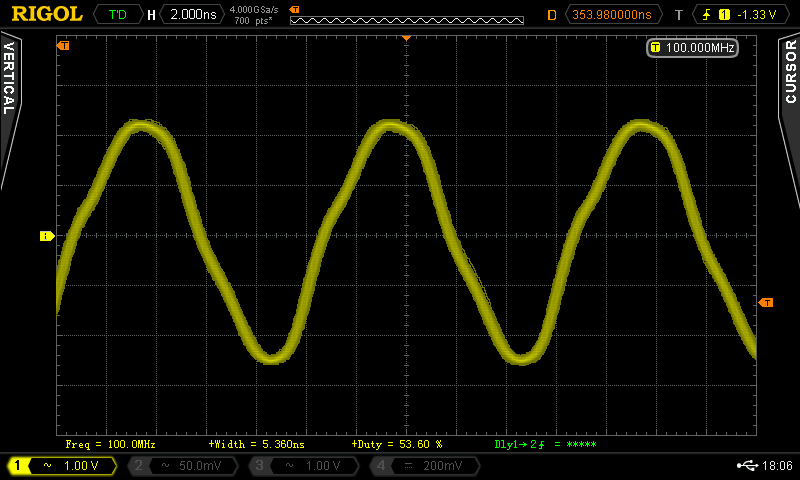
It's interesting that the signal before the buffer right at the quartz looks quite similar, maybe even cleaner:
....
Any feedback is welcome!
Best Regards,
Hermann
What is the bandwidth of your scope?
Hi Acko,
Well come back and Happy New year to you!
You talk about new toys
Regards,
Enrico
Thanks Enrico! Actually I have got this already:
An externally hosted image should be here but it was not working when we last tested it.
New version will have up to 384KHz Fs, DSD64 and DSD128 capability.
Also a 2s FIFO buffer.
The hardware has been tweaked for HiRes Audio as above but the designers are still working on the firmware side for DxD (352.8k, 24bit PCM) and expecting this mid-year. Remote firmware update possible.
Last edited:
Great stuff!
Boards for use with S03 are all on order, expecting in ~2wks:
1. DDDAC-UFL (revised to correct board error)
2. BIII-UFL (2CH)
3. BBB-UFL
3. NDK2520-CCHD950
Will contact those who are on the list as soon as they become available:
Giulio: BBB - UFL (1x) + BIII - UFL (1x) both with UFL mounted - shipped
IanS1: DDDAC-UFL (with UFL mounted) X2 -shipped
Myint67 DDDAC -UFL (with Ufl mounted )x2 -shipped
Stijn001: DDDAC-UFL (with Uf.L.'s mounted) 2x - shipped
Dwjames: DDDAC-UFL (with Uf.L.'s mounted) 1x - shipped
bkdog: BII-UFL - shipped
There are few more of these available. If interested, please add to the above list.
An externally hosted image should be here but it was not working when we last tested it.
An externally hosted image should be here but it was not working when we last tested it.
An externally hosted image should be here but it was not working when we last tested it.
An externally hosted image should be here but it was not working when we last tested it.
Is the last item (BBB-UFL-I2S?) what I'd need to connect a BBB to my S03 for running synchronous? If so, please put me down for one.There are few more of these available. If interested, please add to the above list.
An externally hosted image should be here but it was not working when we last tested it.An externally hosted image should be here but it was not working when we last tested it.An externally hosted image should be here but it was not working when we last tested it.An externally hosted image should be here but it was not working when we last tested it.
ahh, and also 2 of the clock boards
Last edited:
What is the bandwidth of your scope?
I have a Rigol 4024DSO available, which has 4 GSamples / s with an upgrade to 500MHz bandwidth (probes are rated as 500MHz bandwidth, too).
I also thought about measurement failures but if you compare the graphs below it seems strange to me:
1) The 100MHz signal at the FF (pin 3)
2) The BCK signal before the FF (pin 2)
3) The reclocked BCK signal at the FF (pin 5)
On the reclocked signal it seems that most of the signal is below a jitter of 2ns, but as I enabled the display persistence to maximum, the scope records all signals, so the jitter picture is "building up" as can be seen at the edges of the signal..
I used the same setting for the display persistence for the other two signals above, but these signals look very clean to me, the remaining jitter there may very well come from the limitations of my scope, however, for the last picture I doubt that this has something to do with it.
So, for me there are two possibilities:
a) There's really something weird going on in the FF (btw., the FF seems not to be broken as the second FF, used for the LRCK signal, shows the same results, unlikely that they both broke).
b) There is some side-effect which leads to measurement errors and lead to such a picture which I don't understand.
Perhaps someone else has a scope and can post his results?
Best Wishes,
Hermann
Attachments
Hi Acko,Thanks Enrico! Actually I have got this already:
An externally hosted image should be here but it was not working when we last tested it.
Where can I get acess to one of this? Please let us know your findings between this and BBB?
Btw, I will be sending back the S03 tomorrow for your assistance. After followed your instruction, removed R3 and connecting R2 to R4, it is no longer working as it should. I measured the smd R2 with DMM, it said 50R rather 20R as labelled. I think I might applied the heat for too long there.
Lastly, how is your SuperCape? Any update?
Cheers,
Chanh
Last edited:
There are few more of these available. If interested, please add to the above list.
An externally hosted image should be here but it was not working when we last tested it.An externally hosted image should be here but it was not working when we last tested it.An externally hosted image should be here but it was not working when we last tested it.An externally hosted image should be here but it was not working when we last tested it.
triodehunter:
1x DDDAC-U.FL
2x AKX2520
1x BBB-U.FL
Thank You.
Thanks Enrico! Actually I have got this already:
An externally hosted image should be here but it was not working when we last tested it.
The hardware has been tweaked for HiRes Audio as above but the designers are still working on the firmware side for DxD (352.8k, 24bit PCM) and expecting this mid-year. Remote firmware update possible.
Thanks Acko for the infos
@Chan,
This is the email address info@abc-pcb.com and you can ask for availabilty of the NMR_OEM board.
Regards,
Enrico
I take one of each (DDDAC-UFL and BBB-UFL), please. You can send them together when my S03 is returning back to me.There are few more of these available. If interested, please add to the above list.
An externally hosted image should be here but it was not working when we last tested it.An externally hosted image should be here but it was not working when we last tested it.
Chanh
Thanks Enrico. I thought they don't pass on to end user, commercial only? Regardless, I will send them an email. Any idea of cost for a unit?@Chan,
This is the email address info@abc-pcb.com and you can ask for availabilty of the NMR_OEM board.
Regards,
Enrico
Cheers.
Chanh
Thanks Acko for the infos
@Chan,
This is the email address info@abc-pcb.com and you can ask for availabilty of the NMR_OEM board.
Regards,
Enrico
Very interesting looking board.
Thanks Enrico. I thought they don't pass on to end user, commercial only? Regardless, I will send them an email. Any idea of cost for a unit?
Cheers.
Chanh
They will send you the price list. The one that I buy is the Edel NMR and will cost 460 CHF + 90 CHF for the shipment. More or less 550 USD
Regards,
Enrico
James,can anyone clarify which 2 clock frequencies I'd need for synchronous clocking with BBB?
Can I use NDK NZ2520SD in either 22.5792Mhz/24.576MHz or 45.1584MHz/49.152MHz ?
I have mine fitted with 45/49.xx. Apparently, we can set Miero's driver to operate at 45/49.xx also. Previously it was thought not possible which I have had my S03 set with div/2. Lately I have damaged the S03 trying to set it to sync at native fitted clocks frequencies 45/49.xx which was failed.
- Status
- This old topic is closed. If you want to reopen this topic, contact a moderator using the "Report Post" button.
- Home
- Group Buys
- Amanero Isolator/Reclocker GB