Soo, what clocks (4x.xxx / 9x.xxx) would be best suited for this job?
Since it is 7x5mm clocks, the CCHD-957's won't fit the board - what about the Fox XPO-HC735/736 ones? or is there any other one that is easy to obtain which would be better?
What are you guys going to use?
Since it is 7x5mm clocks, the CCHD-957's won't fit the board - what about the Fox XPO-HC735/736 ones? or is there any other one that is easy to obtain which would be better?
What are you guys going to use?
Soo, what clocks (4x.xxx / 9x.xxx) would be best suited for this job?
Since it is 7x5mm clocks, the CCHD-957's won't fit the board - what about the Fox XPO-HC735/736 ones? or is there any other one that is easy to obtain which would be better?
What are you guys going to use?
Can take both 5x7mm and CCHD series 9x11mm XOs. See land pattern.
Attachments
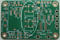
Can take both 5x7mm and CCHD series 9x11mm XOs. See land pattern.
Correction: should have been ..."CCHD series 9x14mm" ...
Also, Q2 is not listed on the BOM. This is needed if dual XO is used and can be the same type as Q1 or other suitable sot23 npn types. Thanks Hochopeper and RollE2K for pointing out!
Thanks Acko got it.
I have been having lots of niggling issues with my BIII/Arduino/Tubeizator build that are largely related to the Arduino doing strange things & these problems have kept me away from the isolator-reclocker mod.
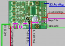
To try & solve my DAC project issues I want to use the S01 board as a I2C isolator in the short term to see if isolating the DAC section from the Arduino section will help. The only link between the sections at the moment is the I2C link to the BIII.
With help from hochopeper, I have come up with the following configuration that I was hoping hochopeper or any other knowledgeable person could check before I give it a run tomorrow.
The intention is to:
I assume I dont need a level changer for the 5V Arduino SCL & SDA lines?
Really all I'm doing here is consolidating what hochopeper has already suggested. I just like to make sure I got it right before I fire up the iron, mind you I'll be lucky to be able to find some of these components, let alone solder them in place.
I have been having lots of niggling issues with my BIII/Arduino/Tubeizator build that are largely related to the Arduino doing strange things & these problems have kept me away from the isolator-reclocker mod.
To try & solve my DAC project issues I want to use the S01 board as a I2C isolator in the short term to see if isolating the DAC section from the Arduino section will help. The only link between the sections at the moment is the I2C link to the BIII.
With help from hochopeper, I have come up with the following configuration that I was hoping hochopeper or any other knowledgeable person could check before I give it a run tomorrow.
The intention is to:
- Populate U2 as the isolator with Si8600 Bi-directional I2C isolator
- Populate C2 & C3 as the isolator by pass caps
- Connect the the Arduino SCL & SDA to the Mute & DSDOE inputs
- Connect the Arduino 3.3V to VS (3.3V In)
- Connect the Arduino GRND at VS
- Connect the the BIII SCL & SDA to the Mute & DSDOE outputs
- Populate C12, C13, C14, C15, FB1 & U7as the regulator section for the BIII 5.25v input
- Connect the BIII 5.25V to J1 & BIII GRND to J1
- Use pullup resistors between J3 & DSDOE & Mute outputs.
I assume I dont need a level changer for the 5V Arduino SCL & SDA lines?
Really all I'm doing here is consolidating what hochopeper has already suggested. I just like to make sure I got it right before I fire up the iron, mind you I'll be lucky to be able to find some of these components, let alone solder them in place.
Attachments
Last edited:
Sounds right to me mate
When you solder the stuff, take your time, first time doing SMT is the same as first time doing anything, you'll feel clumsy for a while, but eventually it'll all come naturally!
Thank you once again
What should I use to clean off the residue?
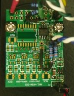
I couldn't get it to work though. The regulators working & everything appears to be ok but when I connected it between the BIII and the Arduino I couldn't get the 2 talking properly. The Si8600 data sheet shows 3K pull up resistors on both sides of the chip off each SCL & SDA leg, so I tried that as you will see in the photo, but even thought I was getting some communication it was far from right.
I couldn't get it to work though. The regulators working & everything appears to be ok but when I connected it between the BIII and the Arduino I couldn't get the 2 talking properly. The Si8600 data sheet shows 3K pull up resistors on both sides of the chip off each SCL & SDA leg, so I tried that as you will see in the photo, but even thought I was getting some communication it was far from right.
Attachments
What should I use to clean off the residue?
natural hair, carbon, or even toothbrush + IPA (scrub) + demineralized/distilled water (scrub), then hot air.
natural hair, carbon, or even toothbrush + IPA (scrub) + demineralized/distilled water (scrub), then hot air.
You want me to scrub it with beer!!.
I googled IPA and the closest thing I could find was an Indian beer.

What is IPA & where do I buy it?
You want me to scrub it with beer!!.
I googled IPA and the closest thing I could find was an Indian beer.
What is IPA & where do I buy it?
Ha ha, Indian Pale Ale - it's not bad.
Although I'd use isopropol alcohol to clean a PCB...
Thanks guys you can buy 1 liter for $10.00 from Isopropyl Alcohol, Industrial Chemicals and Solvents - FREE Shipping Australia Wide but the postage is a killer. Jaycars just down the road so I may do that.
Anyone interested in buying some of this 9188A WH005 Alpha Wire | Mouser
Anyone interested in buying some of this 9188A WH005 Alpha Wire | Mouser
- Status
- This old topic is closed. If you want to reopen this topic, contact a moderator using the "Report Post" button.
- Home
- Group Buys
- Amanero Isolator/Reclocker GB