Hi fellas,
Wanted to update this thread with some measurements of my Alpha Nirvana in my NPXP chassis. Recall that my Alpha Nirvana version has +/-24V rails, gain of ~20dB and about 1.3A bias. I recently purchased a Quantasylum QA403 and I am loving it! You can compare my measurements with those published on page 13 but do note that my vertical scale is in dbV and not dbFs. I do not know of an accurate method of converting the two but keep that in mind they are not equivalent. Moreover, my build uses dual SLB’s and I see that I only used 10mF capacitors in the supply not 15mF! In any case, I’m disassembling my NPXP to put a new module in and will be adding a 32,800uF cap bank per channel.
Unweighted noise

My 60Hz is at -107 to -108 dbV which is about 4 microvolts RMS. That’s pretty much inaudible (my speakers are 95dB sensitive for reference). Also note that this is on a bandwidth of 20Hz to 20khz. If I had hauled out my bench meter that has a 100khz bandwidth, the number would be roughly 5 times worse. That being said, 20 microvolts RMS (@60Hz) is still quite low. The goal for any amplifier design is to be comfortably less than 1mV (1000uV) RMS overall and this one obviously is.
A-weighted:

Of course when you add an A-weighting filter as most manufacturers would, everything looks even better. The belief is that this correlates most with how the human ear perceives relative ‘loudness’ of these frequencies. Depending on your age, due to presbyacusis, your own weighted filter might be more at 4khz on up. Some manufacturers will list CCIR weighted curve which is different and said to be a bit more accurate rendition of what the human ear perceives with regards to ‘random noise.’
1 watt/1khz/8 ohms:

2 watts:

5 watts:

10 watts:

20 watts:

Clipping/30 watts/1% distortion:

That’s all folks. Those of you on the fence should just build this amplifier. It’s a single ended Class A design that‘s very, very polished and a gift to diy’ers. I hope that one day Hugh will share the fruits of his knowledge with a complementary/push pull design but the fella is still pushing it at his age and needs to make a living!
Best,
Anand.
Wanted to update this thread with some measurements of my Alpha Nirvana in my NPXP chassis. Recall that my Alpha Nirvana version has +/-24V rails, gain of ~20dB and about 1.3A bias. I recently purchased a Quantasylum QA403 and I am loving it! You can compare my measurements with those published on page 13 but do note that my vertical scale is in dbV and not dbFs. I do not know of an accurate method of converting the two but keep that in mind they are not equivalent. Moreover, my build uses dual SLB’s and I see that I only used 10mF capacitors in the supply not 15mF! In any case, I’m disassembling my NPXP to put a new module in and will be adding a 32,800uF cap bank per channel.
Unweighted noise
My 60Hz is at -107 to -108 dbV which is about 4 microvolts RMS. That’s pretty much inaudible (my speakers are 95dB sensitive for reference). Also note that this is on a bandwidth of 20Hz to 20khz. If I had hauled out my bench meter that has a 100khz bandwidth, the number would be roughly 5 times worse. That being said, 20 microvolts RMS (@60Hz) is still quite low. The goal for any amplifier design is to be comfortably less than 1mV (1000uV) RMS overall and this one obviously is.
A-weighted:
Of course when you add an A-weighting filter as most manufacturers would, everything looks even better. The belief is that this correlates most with how the human ear perceives relative ‘loudness’ of these frequencies. Depending on your age, due to presbyacusis, your own weighted filter might be more at 4khz on up. Some manufacturers will list CCIR weighted curve which is different and said to be a bit more accurate rendition of what the human ear perceives with regards to ‘random noise.’
1 watt/1khz/8 ohms:
2 watts:
5 watts:
10 watts:
20 watts:
Clipping/30 watts/1% distortion:
That’s all folks. Those of you on the fence should just build this amplifier. It’s a single ended Class A design that‘s very, very polished and a gift to diy’ers. I hope that one day Hugh will share the fruits of his knowledge with a complementary/push pull design but the fella is still pushing it at his age and needs to make a living!
Best,
Anand.
Last edited:
Blowmymind,
Looks like you have plenty of DIY experience.")
I didn't build the AN39, but built its predecessor (if it can be called as such) the ALPHA 20, whch is also a design by Hugh Dean. The AN39 is an improved design by Hugh, both in terms of output performance and power efficiency. In have built other solid state amps, and a few low watt HiFi tube amplifiers too. Nowadays no more tubes for me.
Looks like you have plenty of DIY experience.
I didn't build the AN39, but built its predecessor (if it can be called as such) the ALPHA 20, whch is also a design by Hugh Dean. The AN39 is an improved design by Hugh, both in terms of output performance and power efficiency. In have built other solid state amps, and a few low watt HiFi tube amplifiers too.
Nowadays no more tubes for me.Hi, I already got the pcb's from X's store and the Toroidy 2x18v 400vac transformer for the Alpha Nirvana 20w//8ohms version.
I'm also finishing the bill of materials for different electronics companies.
I was wondering if someone could help me debug the 20w circuit. My questions are reflected in post#3000 and #3001. I am sorry, as I would like to have a higher level of electronics and see things more clearly.
Regards
I'm also finishing the bill of materials for different electronics companies.
I was wondering if someone could help me debug the 20w circuit. My questions are reflected in post#3000 and #3001. I am sorry, as I would like to have a higher level of electronics and see things more clearly.
Regards
Sorry karucho I can't help with your questions but I hope you enjoy the build and have a successful outcome.
I've been re hashing my AN39. The Capmx psu was running too hot so I thought I'd try a CRC. Got it going but obviously I'm not dropping the same voltage as the Capmx and now I'm at 35v rails unloaded and about 32 loaded. What with my high bias it is too much dissipation. Maybe I need to use my 18v trafo but then I lose my dual mono PSU!
Oh the decisions!
jimk04,
What is your transformer secondary voltage? Is it 25V AC? That should give you around of 35V DC (before load) using a CRC power supply.
For +/-30V DC on the PSU rails before load, you will need a transformer that has 2x22V AC secondaries. With a 3 volt drop due to the load, you will end up with +/-27V.
With a transformer with 18V AC secondaries you will be probably running at +/- 22V after load.
It is rated at 23v @ 230v but as usual I have quite a bit higher than that at the mains so it does give approx 25v unloaded yes.
It's just that it had quad secondaries to allow dual mono that made me want to use it but I think I'll have to swap it out.
My LT4320s don't help here either!
Or I crack on and build tombo's R21 regulators which will afford me maybe 4v drop.
It's just that it had quad secondaries to allow dual mono that made me want to use it but I think I'll have to swap it out.
My LT4320s don't help here either!
Or I crack on and build tombo's R21 regulators which will afford me maybe 4v drop.
Hi
My AN39 at 4 Ω 0.11Ω source resistor with trafo 18V at 3.1A ,LT4320-CRC-Cap multiplier = 20V-20.30V
at 2A 0.18Ω source resistor , LT4320-CRC-Cap multiplier = 21,5V-21.80V
im waiting the classical diodes STPS20M60D to see what happen ....
I don't expect big differences in the voltage but only a little more temperature which will be solved with the help of a cooler in between diodes.
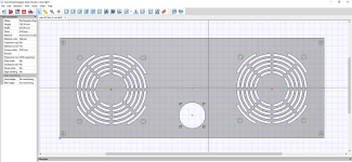
For me, this amplifier, when it goes into its box, also needs a fan at the top to take the air from the inside of the box.
It really depends on which version you have made and how many amperes bias....3A
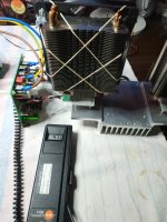
the problem with mosfet at 3 A amperes is not so much the heat dissipation from the main heatsink but the trapped temperature in the mosfet housing...
i think i solved.....
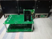
temp room 20C i have at 3.1A bias 41.5C on fan active heatsink at the bottom copper .
and the flow of the fans is very small and they are not heard at all.
I also did a test with classic heatsinks at 3A, NOT FOR A JOKE......Body temp mosfets .....too hoooooot.
My AN39 at 4 Ω 0.11Ω source resistor with trafo 18V at 3.1A ,LT4320-CRC-Cap multiplier = 20V-20.30V
at 2A 0.18Ω source resistor , LT4320-CRC-Cap multiplier = 21,5V-21.80V
im waiting the classical diodes STPS20M60D to see what happen ....
I don't expect big differences in the voltage but only a little more temperature which will be solved with the help of a cooler in between diodes.
For me, this amplifier, when it goes into its box, also needs a fan at the top to take the air from the inside of the box.
It really depends on which version you have made and how many amperes bias....3A
the problem with mosfet at 3 A amperes is not so much the heat dissipation from the main heatsink but the trapped temperature in the mosfet housing...
i think i solved.....
temp room 20C i have at 3.1A bias 41.5C on fan active heatsink at the bottom copper .
and the flow of the fans is very small and they are not heard at all.
I also did a test with classic heatsinks at 3A, NOT FOR A JOKE......Body temp mosfets .....too hoooooot.
Attachments
Last edited:
Hello again, I am still with my doubts exposed in posts #3000,#3001 about the 20w +/-20v version.
I am going to ask it in another way.
In the 4R +/-21v version made by Andyr I have seen value changes in the resistors where I have my doubts. As the supply voltage is very similar, what do you think about using their values? it is an assembled and adjusted circuit.
The exception would be for R141 and R142 which determine the quiescent value.
--39w +/-27v------ 4ohms +/-21v------20w +/-20v "Hugh simulation"--
.R111--3K3..............3K3................................1K75 (R4)
.R112--6K8...............5K.................................5K6 (R5)
.R113--22R pot.......pot................................pot
.R121--1K5...............820R............................1K (R8)
.R122--2K2................1K2..............................1K5 (R9)
.R132--1K...................820R...........................1K (R21)
.R161--20K.................14K7............................ ----
.R162--20K.................14K7............................ ----
.R141--0R22..............0R12.............................0R27 (R15)
.R142--0R22..............0R12.............................0R27 (R16)


Regards
I am going to ask it in another way.
In the 4R +/-21v version made by Andyr I have seen value changes in the resistors where I have my doubts. As the supply voltage is very similar, what do you think about using their values? it is an assembled and adjusted circuit.
The exception would be for R141 and R142 which determine the quiescent value.
--39w +/-27v------ 4ohms +/-21v------20w +/-20v "Hugh simulation"--
.R111--3K3..............3K3................................1K75 (R4)
.R112--6K8...............5K.................................5K6 (R5)
.R113--22R pot.......pot................................pot
.R121--1K5...............820R............................1K (R8)
.R122--2K2................1K2..............................1K5 (R9)
.R132--1K...................820R...........................1K (R21)
.R161--20K.................14K7............................ ----
.R162--20K.................14K7............................ ----
.R141--0R22..............0R12.............................0R27 (R15)
.R142--0R22..............0R12.............................0R27 (R16)
Regards
Last edited:
Hmmm....... I would change R111 from 3k3 to 3k, and include a 1k for pot R112. Then adjust that pot to achieve 0mV output offset.
Since you are changing the voltage from 21V to 20V, I would change no other resistors or caps.
The only proviso here is R141 and R142 (both EQUAL) and should you wish to use the amp with 4R I would suggest decreasing them to 0.15R each to set a quiescent of close to 3A.
Good luck with your 4R AN!
Hugh
Hugh, I thank you very much for your reply and advice on the way forward with some small changes in the circuit. You are surely a very busy person and this gesture makes me very happy
I must say that I am going to mount the "Alpha Nirvana 20w//8 ohms +/-20v" version and as I believe that nobody has mounted this version here I leave the changes waiting to be able to mount it:
R111-3K , R112-5K , R113-1K pot , R121-820R ,
R122-1K2 , R132-820R , R161-14K7 , R162-14k7
R141-0R27 , R142-0R27
Thanks again
Regards
Sorry, I am unable to check your res values but your statement "I am going to mount the 'Alpha Nirvana 20w//8 ohms +/-20v" version and as I believe that nobody has mounted this version here' " has caused me to respond.
The original version of the Alpha Nirvana was 40w into 8 ohms - with +/-27v DC rails.
Hugh then produced the modified (of some component values) version - 40w into 4 ohm spkrs. This is the one that I built - and has +/- 20 or 21v DC rails.
Andyr,
thanks for the clarification and apologies for my incorrect statement.
The thing is that there are a few schematics around here and I'm a bit confused.
What I was trying to say was that I am going to use the "+/-21v 4R" construction of model to follow, with the corresponding resistor changes except R141-R142 which in my case will be an 8 ohms version changing only 0R27 in R141 and R142 (quiescent of close to 1'7A).
I could also use the values reflected in the 20w//8ohms version of the simulation that Hugh did, but I have preferred to use the values of an assembled and tested version as is the "4R" version only with the changes cited above (R141-R142).
I hope that my reasoning is the right one and that's why I have some questions about my doubts.
Best regards
Hi AndyHugh then produced the modified (of some component values) version - 40w into 4 ohm spkrs. This is the one that I built - and has +/- 20 or 21v DC rails.
Can i ask you something ? once you make the version 4R same story here
...
Which is the bias Ampere that you set your amp?
Did you put also the capacitor C134 2200pf?
I see your construction in a box how about the temperatures ?
Last edited:
- Home
- Amplifiers
- Solid State
- Alpha Nirvana 39w 8ohm Class A Amp