Those look genuine.I would like your opinion if it is genuine, I found it in a local store here in Greece.
Thanks .
Yes, it's a very good device but take care with the pinouts.
Hugh
Hugh
2SD668ASI NPN transistor | ||
| UCE/UCB | 160/180V | |
| IC DC/AC | 50/100mA | |
| hFE | - | |
| Ptot | 20W | |
| fT | 140MHz | |
| TJ | - | |
| the 2SD668A is a silicon NPN transistor, Uce = 160V, Ic = 50mA, applications: audio frequency stage, power transistor, switch, video transistor |
The NTC provides a higher level of safety because if there was a short in the power rail or MOSFET - it can flow a lot of current (if needed as temp drops resistance to 0.5ohms) without blowing out and going open circuit. Diodes only flow 1A for small ones. 10A ones are much larger and more expensive than an NTC.
Making a bit of progress on my dual mono setup. I have mounted the CPU heatsinks onto the Noctua F9 fans. Just for grins I hooked up the fans and gave them a listen. They are very quiet, even at high speed. I now need to attach some Mfets to the cpu heatsinks. I have a lot of Molex minifit sockets and receptacles I would like to use up, so have a couple of questions:
1. Will it hurt anything to fully populate the Mfet snubber / helper boards even though I have the snubber portion populated on the dual SLB board.
2. Any problems with clamping the Mfet snubber / helper board and the Mfet to the cpu cooler heatsink, rather than just clamping the Mfet to the cpu cooler. As I mentioned above, I would like to use up some Molex sockets / receptacles.
Thank you for your help with this. Will post some pics soon, once I get a few more chassis parts made.
MM
By Myles,
Are you asking if it’s ok to install both the gate stopper resistor on the main PCB and on the snubber board? No, not a problem. Really not much difference between 100ohm vs 200ohm on the gate stoppers.
The snubber boards that look like a tombstone were meant to act also as the mosfet clamp washer. They are 2mm thick and very stiff. Use them above the mosfet and the M3 bolt should canon the snubber down with the MOSFET underneath it.
Line up the hole on the MOSFET with the hole indicated in red here and that lets you use it as a clamp washer.

You can solder wires as flying leads to the rectangular pads or to the holes. I find that there is less strain on the wires if they lay flat along axis with snubber.
Line this:

Are you asking if it’s ok to install both the gate stopper resistor on the main PCB and on the snubber board? No, not a problem. Really not much difference between 100ohm vs 200ohm on the gate stoppers.
The snubber boards that look like a tombstone were meant to act also as the mosfet clamp washer. They are 2mm thick and very stiff. Use them above the mosfet and the M3 bolt should canon the snubber down with the MOSFET underneath it.
Line up the hole on the MOSFET with the hole indicated in red here and that lets you use it as a clamp washer.
You can solder wires as flying leads to the rectangular pads or to the holes. I find that there is less strain on the wires if they lay flat along axis with snubber.
Line this:
Last edited:
Hi X, thanks for the help. Not quite sure about the use of the M3 bolt, as I will be using a metal bar to hold the Mfet against the copper pad on the cpu cooler.
So, I guess my question would be: Can I use these tombstones between the metal clamp bar and the Mfet.
If I can use them, I will use the Molex connectors from cpu cooler to the amp module. ( I need to use up my inventory of Molex connectors") )
)
If I cannot use them I will clamp down the Mfet with the metal bar and use a couple of the smaller blue color Mfet helper boards I purchased from you and attach the molex connectors from cpu cooler to the amp module.
I may consider laying the wires on the pads and soldering.
Let me know your thoughts,
MM
So, I guess my question would be: Can I use these tombstones between the metal clamp bar and the Mfet.
If I can use them, I will use the Molex connectors from cpu cooler to the amp module. ( I need to use up my inventory of Molex connectors
)If I cannot use them I will clamp down the Mfet with the metal bar and use a couple of the smaller blue color Mfet helper boards I purchased from you and attach the molex connectors from cpu cooler to the amp module.
I may consider laying the wires on the pads and soldering.
Let me know your thoughts,
MM
Myles it sounds like you will do things how I am and here is my suggestion. Sorry I don't have a photo yet as I haven't actually got the snubbers in place yet. Ongoing job. Minimise the gap between the clamp and the mosfet. Insulate against shorts if needed. And like X said id have the wires running along the axis of the PCB, not in the holes at 90degrees.
Attachments
Last edited:
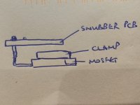
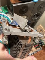
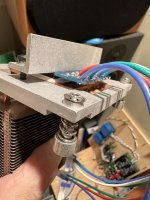
Thanks Jim for the info. In an effort to show what I am working with, please see the attached mock up's of my layout and your layout. Focus on where the Mfet is, as there are other snubber boards used, just to level things. Image from left is the fan/hs layout, next is Jim's top view, next is Jim's end view where the clamp is against the Mfet and snubber board on top.


Below is a top view and end view of my mounting procedure with snubber board against the Mfet and clamp on top.


I am not sure which way to go: Using Jim's layout the Mfet legs stick up thru the snubber board with no problem. Tapping the copper to hold the snubber board could be a problem. I may be able to attach a spring type clip to hold the snubber board in position.
Using Myles's layout the Mfet legs stick up thru the snubber board with no problem also. It may have a potential problem with having enough clamp down force to ensure Mfet and snubber board do not move around. The copper clamp I will use weighs a fair bit on its own, so clamping force applied may be minimal.
Comments and suggestions are welcome.
Regards,
MM
Below is a top view and end view of my mounting procedure with snubber board against the Mfet and clamp on top.
I am not sure which way to go: Using Jim's layout the Mfet legs stick up thru the snubber board with no problem. Tapping the copper to hold the snubber board could be a problem. I may be able to attach a spring type clip to hold the snubber board in position.
Using Myles's layout the Mfet legs stick up thru the snubber board with no problem also. It may have a potential problem with having enough clamp down force to ensure Mfet and snubber board do not move around. The copper clamp I will use weighs a fair bit on its own, so clamping force applied may be minimal.
Comments and suggestions are welcome.
Regards,
MM
I believe you’re overthinking this setup Myles.
Forget the copper bullion as a clamp. Aluminum angle won’t bend, drill and tap M4 holes in the aluminum base for the clamp fasteners.
Use the little blue boards and solder the snubber components directly to the legs.
Forget the copper bullion as a clamp. Aluminum angle won’t bend, drill and tap M4 holes in the aluminum base for the clamp fasteners.
Use the little blue boards and solder the snubber components directly to the legs.
Attachments

Hi Vunce,
Thanks for the info. I know you are a big proponent of the angled aluminum. The piece of copper I have is 1/4" thick and about an inch wide. Over the width of the heatsink, I do not expect any significant bending. I will drill the copper and drill/tap the aluminum. I need to use up inventory I have rather than buying more, but, just in case the copper does not work , please remind me of the dimensions of the angled aluminium, especially the thickness.
I do like the idea of attaching the blue helper boards to the Mfet legs and I happen to have some of these in my inventory. From your photo's I gather that the resistors, caps, diode, are soldered on the bottom of blue boards ?.
Since my heat sinks will be laying horizontal, the Mfets will be mounted vertically. I plan to use Molex connectors / cabling. This brings a choice of mounting the Mfets / blue boards facing upward or downward. Any advantage cabling / strain wise for either mounting direction (ie: wires hanging downward or wires on a slight incline to the amp boards. ?
Thanks for the help always, sorry to ask so much
Myles
Can someone compare or share their experience with this amp sound with other class A amps like Aleph J2, Fist Watt F5, F6 etc?
This is what I listened to previously and the Alpha Nirvana is better in every way:
https://www.diyaudio.com/community/...ters-platform-npxp.373417/page-3#post-6790487
Here is a review vs Class D:
https://www.diyaudio.com/community/...8ohm-class-a-amp.344540/page-112#post-6987070
I kindly suggest others to write review comparisons.
Best,
Anand.
https://www.diyaudio.com/community/...ters-platform-npxp.373417/page-3#post-6790487
Here is a review vs Class D:
https://www.diyaudio.com/community/...8ohm-class-a-amp.344540/page-112#post-6987070
I kindly suggest others to write review comparisons.
Best,
Anand.
Hi guys, I want to make a power supply for the Alpha Nirvana 4R. I am interested in a CRC variant... Can you recommend a scheme with suitable values for this project?
Has anyone used this type of simple power supply ?
Thank you
NO! Use X's SLB PS.
@knauf1919
The answer is…no it’s not. But there may be some things to explain first. First understand and remember, this is NOT a push pull design. This is a single ended Class A design, so the power supply rejection ratio is typically not as good to an equivalent push pull/complementary design. This puts some practical limitations/requirements to the power supply design as the load impedance drops (assuming we are talking about driving speakers, not headphones 😉).
Compared to an 8 ohm version of the Alpha Nirvana, the 4 ohm version demands from the power supply a much higher amount of current because the bias level is much, much higher. It’s not 1.7A. It can be up to double that.So let’s be a little more conservative and say 3A of bias per channel. In practice, you’ll need a CRCRC or even more multiples of that in order to drop the ripple from your AC main supply (in example 50Hz in Europe and 60Hz in North America) to low levels so you don’t hear hum from the amplifier. You can use the supply from the diyaudiostore or Randy Thatcher’s supplies from his etsy store, or a multitude of other examples. Just be sure that you use enough capacitance. Randy’s V8 supply uses 88mF/rail (4*22mF per the schematic). It is a CCRCRC design. That looks good enough if you used 1/channel. You can use a CLCLC supply but that is expensive too. But I haven’t tested those examples, so you are on your own. You can also model these supplies on Duncan’s PSUD2 program available for free online. The simulation will show you how much ripple is present at the tail end of the supply when loaded. I aim for <100mV RMS as a minimum.
But there is an easier way.
X’s SLB supply is CRC + capacitance multiplier that has been tested to 4A currents with < 10mV RMS of ripple. The measurements are in the link.
X’s commercial version of this amplifier (the Verafi brand), is an 8 ohm version of this design using a simpler CRC design but of course, MUCH lower current requirements, i.e. 1.7A/channel.
If you want a simple supply, build the 8 ohm version. If you want a true 4 ohm version, the power supply will be more expensive and a little more complicated by definition of the electrical standards imposed by the design.
The moral of the story is this. How a power supply is designed depends on the amplifier’s design topology, class of topology (i.e. Class A, AB, single ended Class A or push pull Class A), power output (i.e. headphones demand less), and of course, bias current. If this is difficult to understand, I suggest addressing the gaps in your knowledge base to better appreciate this. Duncan’s PSUD2 is a good start to see how this pans out in the real world.
Best,
Anand.
Last edited:
I used Prasi/Gtose/Johnson capacitance multiplier PSU on my 4R build with good success.Is it the one and only option?
Hi my friend.I used Prasi/Gtose/Johnson capacitance multiplier PSU on my 4R build with good success.
Which is your bias/voltage on your 4R build?
Did you measure the ripple out?
Bank cap in uf ?
And how about temp from this Psu rectifiers?
BR Nikos
- Home
- Amplifiers
- Solid State
- Alpha Nirvana 39w 8ohm Class A Amp