I use 6550s connected as triode, with 450V, without any problem.
I have a Simple SE with EH KT-88's in it. B+ is 475 volts with about 425 volts across the tube (cathode bias + OPT loss). I have it biased at about 100 mA because the bass on my OB speakers sound better at high currents. It has a triode / UL switch in it, and I use it in either mode depending on how loud I want to get and what kind of music I am playing. This amp still has the original pair of tubes in it and they are about 2 years old.
The amp has been flawless since initial power up except for a blown pair of IXYS FREDs which were replaced with Fairchild Stealths. The amp was built on a chassis that is too small, and the Hammond made Allied 6K7VG power transformer that is rated for 150 mA gets rather toasty at 220 mA!
I have run Chinese 6L6GC's and various EL34's in the same amp at a much lower current and 435 volts of B+, and again no problems. Do not do this with 6L6GA's or GB's. They don't like 400+ volts on the screen, I have seen the glow of death inside them!
I started this thread because of contradictions in 6V6 spec sheets
I have banged on a few 6V6GT's. They are not all the same. The GE data shows 315 volts in triode mode vertical amplifier service. I have seen no issues with most 6V6's at this level. Many 6V6GT's work at 350 volts in triode. Some of the new production Russian tubes smile at 400 volts in triode or UL mode. I have also blown an old GE into next week by plugging it into the socket when the power supply was still set to 400 volts.
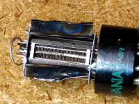
There was a thread a year or two ago where I purposely melted a few worthless Sylvania 6V6GT's. I don't remember the exact details of the carnage, but this is the end result.
Attachments
This doesn't happen in triode (and in ultralinear, since screen voltage dips with plate).
It seems to me like the screen would always be higher than the plate in ultralinear, right?
It seems to me like the screen would always be higher than the plate in ultralinear, right?
The screen idles slightly higher than the plate, due to ratio of DC resistance in the transformer. On negative peaks, it will dip less than the plate, but will drop below idle B+. On positive peaks it will not go as high as the plate. Depending on the B+ voltage, screen resistors might be a good idea... though I've seldom seen them in commercial designs.
Right, I guess I didn't think that through before wording my sentence. What I meant to say is that the plate will be below the screen for the whole negative half of the cycle. It seemed like you were trying to say that it stayed above like the triode case.
I would imagine that an ultra-linear operated pentode would have some pretty good screen current when pushed into saturation. A triode-connected pentode would probably have much less screen current in saturation but then you will have massive amounts of control grid current to deal with, and control grids are much more fragile than screens. I have a set of dead KT88s to prove it.
I would imagine that an ultra-linear operated pentode would have some pretty good screen current when pushed into saturation. A triode-connected pentode would probably have much less screen current in saturation but then you will have massive amounts of control grid current to deal with, and control grids are much more fragile than screens. I have a set of dead KT88s to prove it.
Screen in the same potential...
Tubelab, I want use a 24A small power tetrode in triode mode.
I will put 150V in the plate. The maximum screen voltage is 90V...
I will connect the screen to plate with a 1000 ohms resistor in serie...this work or my screen will be destroyed ???
Thanks,
Aldovan
I have also managed to blast the screen grid out of a 6EJ7 with the screen and plate connected directly together. I think oscillation might have been the cause. A resistor will fix this in either case.
Yes, some caution shound be advised when exploring the limits of a tube that has not been explored before. As pointed out, a resistor of at least 100 ohms should be placed in series with the screen grid as a current limiter and an oscillation stopper. 100 ohms is a good place to start with most tubes. Some tubes need a higher value, with 1000 ohms being the likely upper limit. The EL34 is one tube that wants more than 100 ohms, with 1000 ohms being mentioned in the original Mullard literature. If distortion measuring equipment is available test the distortion with several resistor values and pick the highest value that does not raise the distortion.
I have successfully operated several tubes well above their published screen ratings without issues in triode mode. In many cases you can not approach the plate voltage ratings. This is true with all sweep tubes and some RF tubes like the 807.
It has been stated that the usual 1/2 watt "stopper" resistor is sufficient since the dissipation in the resistor is low. I have found this not to be the case if the amp will ever see clipping. An EL34 can draw some fairly high screen grid current peaks when overdriven. I have fried a few 1/2 watt resistors, and now use a 1 or 2 watt resistor in all of my amps.
Tubelab, I want use a 24A small power tetrode in triode mode.
I will put 150V in the plate. The maximum screen voltage is 90V...
I will connect the screen to plate with a 1000 ohms resistor in serie...this work or my screen will be destroyed ???
Thanks,
Aldovan
I found the following statement in Norman Crowhurst's High fidelity sound engineering (Newnes, 1961, p. 124):
"Many valves, operated as pentodes, require usage of a screen voltage lower than the anode supply voltage. This is because the screen grid gets much more than its share of current in the upswing (anode voltage downswing), so that its voltage must be reduced. Working as triodes, the same valves can use a higher screen voltage, the same as the anode, because the high current upswing is avoided by signal voltage drop. The same thing, happening to a lesser extent, permits the full anode supply voltage to be used also on the screen in ultra-linear working." [my emphasis]
Presumably this means that as long as we don't violate the maximum anode voltage, we can stop worrying about the maximum screen voltages quoted on spec sheets when we use pentodes as triodes. What do our gurus think?
Barreter
I have the same doubt:
I want use a 24A small power tetrode in triode mode.
I will put 150V in the plate. The maximum screen voltage is 90V...
I will connect the screen to plate with a 1000 ohms resistor in serie...
I do not know if the screen will be burn...
But I will make a test...
Aldovan
Tubelab, I want use a 24A small power tetrode in triode mode.
I have never used the 24A so I have no experience on how it will behave. Put a resistor in series with the screen and gradually reduce it while watching how the screen current and plate current behave. If anything starts changing quickly, or you suddenly need a lot more grid bias to control current, something bad is about to happen.
I have never used the 24A so I have no experience on how it will behave. Put a resistor in series with the screen and gradually reduce it while watching how the screen current and plate current behave. If anything starts changing quickly, or you suddenly need a lot more grid bias to control current, something bad is about to happen.
Thanks, I will use a pot for the test.
What value of resistence you recommend for begin the experience ?
Aldovan
I think that fixed well regulated screen grid voltage allows to make better (more linear) triode from pentode applying parallel feedback from anode to the 1'st grid.
It is not the only way to get triode characteristics by connecting screen grid to anode. Another way is to supply AC from anode to the control grid, this way is more flexible and more linear than better known one, "screen to anode".
However, input resistance is lower such a way, but considering Miller capacitance anyway similar driving current is needed for better than average performances.
Wavebourn, I am very interested in this type of triode connection. Can you please show me some examples, preferably on a schematic or drawing?
1.) Is this similar to the "shade" feedback connection? From what I understand, triode connected pentode is really a form of feedback. I know it's trendy for audiophiles to demonize feedback but in an pentode output stage, feedback is absolutely necessary. When apply sensibly, FB is an excellent tool!
2.) How much is the anode's signal fed back to the control grid to qualify as "triode" or triode performance?
3.) Another question on anode-to-screengrid triode connection: is it possible to feed back via a coupling cap to the screengrid while supplying a lower voltage than the plate through a voltage divider from the B+ or UL tap?
Thank you in advance for any comment you may make.
Feedback from anode to g1 is the anode-follower configuration, analogous to the inverting opamp. You should be able to find this described in any good valve textbook.
It has now become trendy to call this 'Schade' feedback. It doesn't turn a pentode into a triode; it becomes a pentode with resistive feedback. Both input and output impedances are reduced, so the previous stage has to work harder. Assuming the previous stage is a triode, working into a low impedance makes its own 'triode distortion' more apparent which may be why people think the whole thing acts/sounds like a triode. On balance it may improve things.
It has now become trendy to call this 'Schade' feedback. It doesn't turn a pentode into a triode; it becomes a pentode with resistive feedback. Both input and output impedances are reduced, so the previous stage has to work harder. Assuming the previous stage is a triode, working into a low impedance makes its own 'triode distortion' more apparent which may be why people think the whole thing acts/sounds like a triode. On balance it may improve things.
- Status
- This old topic is closed. If you want to reopen this topic, contact a moderator using the "Report Post" button.
- Home
- Amplifiers
- Tubes / Valves
- Allowable screen voltages in triode-connected pentodes