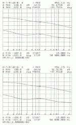
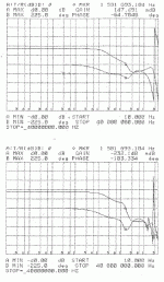
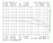
Here are the gain-phase plots of the RIAA preamp channels. Matching is ok, but the gain is high on both channels - I'd like to see around 40 dB gain at 1 kHz rather than 46. This will take a couple of resistor tweaks, but I want to revisit my simulations to see whether it is advisable to shave the excess gain from one stage or both.
Attachments
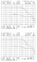
Here are the gain-phase plots of the line amps. Two things need to get fixed here. The first is that the gain on the top plot is low. The second is that both channels need to cross 0dB gain at some point and stay below there. This is easily done by adjusting the value of one of the stopper resistors in the line amp to introduce a a roll-off somewhere around 1-2 MHz. I'm divided as to whether to introduce the pole at the input mosfet or at the P-channel output stage. My tip of the hat would possibly be to slow down the p-channel stage in order to leave the input stage and its summing node fast.
Attachments
Last edited:
The excess gain in the RIAA amp appears to be concentrated in the first folded cascode stage - easily remedied by a couple of resistor value shifts - more on that later. I found a solder splash one one of the line amp channels that might account for the low gain. A re-measurement will determine that.
If people are scratching their heads about the RIAA gain-phase plots a couple of posts ago and wondering what I was talking about, this is what I really meant, as the previous post showed ~36 dB gain at 1kHz vs. the 46 dB I was claiming. I think I have that fixed, too, but I need another run on the analyzer to see.
Attachments
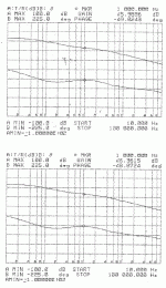
After some resistor tweaks (both gain stages needed adjustment), here are the RIAA gain-phase curves for both channels of the new All-In-One board. 1kHz gain is around 41 dB, reasonably close to the 40 dB target, and both channels match to within 0.3 dB, not too shabby for a relatively complex open loop design. Schematic will follow when I have to time to set it down including tweaks.
Attachments
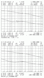
The line stage portion was a little bit harder to fix, and required a Zobel network to keep the gain pushed down below 0dB after crossover. The attached plots show the gain-phase without Zobel (top plot) and with a 2n2 + 22R Zobel network at the output (bottom plot). The gain-phase curves are not anywhere near as pretty as I'd like, but gain and phase margin are sufficiently decent that I can proceed to listening to the blasted thing. Later on, I may try bearing down a little bit harder on the compensation to move in the crossover frequency - there's no real need to have response out past a MHz. Schematic for this version will follow when I get some time to document all the changes.
Attachments
If that is the gain crossing zero dB at the marker then it is too steep at that frequency.
Look up at the no Zobel the steepness at the marher is just on the knee where 6dB/octave changes to 12dB/octave.
The maximum steepness allowable for the gain crossing is ~9dB/octave.
But anything steeper than 6dB/octave generally has an overshoot that affects the audio.
Look up at the no Zobel the steepness at the marher is just on the knee where 6dB/octave changes to 12dB/octave.
The maximum steepness allowable for the gain crossing is ~9dB/octave.
But anything steeper than 6dB/octave generally has an overshoot that affects the audio.
True, but I was even more worried about the gain trying to push itslf back up through zero again after cross it once. I had to practically beat the circuit into submission to get it to cross zero dB and stay down. Starting the gain roll-off earlier should help matters a bit. I'm also going to try a different circuit position for the HF pole. I may try hitting the line amp as-is with a fast square wave to look for overshoot and ringing.
This stuff is all happening on borrowed and stolen time, so it will take a bit whatever I do.
This stuff is all happening on borrowed and stolen time, so it will take a bit whatever I do.
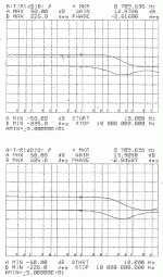
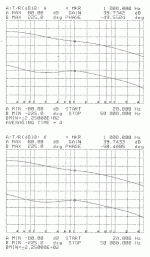
Moving the place in the circuit where I introduced my second compensation pole worked wonders, getting rid of the nasty bumps in the gain and phase. The resulting Gain-Phase plot looks reasonably civilized.
The plot included shows both channels. The top plot shows one channel with the marker placed at the 0dB gain crossing frequency, showng crossover frequency and phase margin. Both 0dB and zero phase are the dead center line on the plot.
The second plot shows the other channel, with the marker shifted to show the mid-band gain and phase - 13.89 dB, with essentially zero phase shift. 13.89 dB works out to a gain of 4.95X, close enough to 5X for my purposes.
The plot shows that I could push in the second pole a little bit more, but I'm tired of messing with this board, and the Gain-Phase shown is quite acceptable - time to plunk it into the test bed for a listen, which is the object of this whole ridiculous exercise in the first place.
Attachments
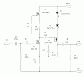
Here's the line amp circuit I'm using for this rev of the All-In-One board. It uses the BSS159, my new depletion mode darling, as gain element. Gain-Phase plots are shown in the previous post. Listening? I'll find out when I have a chance to load this board into my test box.
Attachments
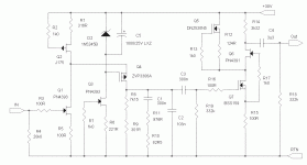
Here's the circuit for the RIAA section of the new preamp board - it's the first time I've tried a single-ended folded cascode circuit for the first stage of the preamp.
I was gratified to be able to shift voltages around to get a reasonable voltage across the front end jfet with a single +30V supply - a +/- 15V supply would have made matters simple, but that's not how my test bed is set up.
I'll talk about setup and fet selection procedures for the line amp and RIAA amp if people are sufficiently interested to ask for them.
BTW, there is a subtle difference in how the RIAA equalization is implemented for this circuit - can you spot it?
Attachments
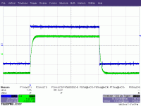
After all the messing about with the frequency response of the line amp shown in post #50, I thought it would be instructime to show the time-domain consequences of the fiddling in the frequency domain. The input to the line amp as shown in the attached scope picture (blue) is a 10kHz square wave from a function generstor, with +/- 400 mV excursion around zero.
The ourput (green) is a damped square wave with excursion of +/- 2V, as would be expected from a line amp with a gain of +5. The response is overdamped, as would be expected from a system with adequate phase margin. How boring - but then, that's the way it should be...
The ourput (green) is a damped square wave with excursion of +/- 2V, as would be expected from a line amp with a gain of +5. The response is overdamped, as would be expected from a system with adequate phase margin. How boring - but then, that's the way it should be...
Attachments
Last edited:
It's important to note that if you're doing a square wave response test as shown in the previous post, it's essential to properly set up the compensation of the scope probes beforehand. Otherwise, you might be fooled by what appears to be overshoot, but in reality is the result of improperly compensated scope probe. You can also be lulled by a test result that appears to be bland and overdamped, but only looks so because the probe is out of kilter.
Last edited:
OK - I threw the latest all-in-one board into my test jig for a listen a couple of weeks back. No problems with the line amp - smooth and clean, which means I have three reasonable options for a line amp - two non-inverting solutions (with global feedback, albeit a very short loop) and one inverting open loop solution requiring a lowish resistance volume pot.
The phono section is a different story. The current solution using a folded cascode first stage sounded rather hot compared to previous solutions, perhaps indicating a fairly gross equalization error, or maybe another more subtle problem. The first thing to try might be a scan with a reverse RIAA network feeding the input, to see if there are gross equalization errors due to some fundamental misunderstanding/simple screw-up. I'll digress later to show you the difference between what I'm trying this time around vs. usual practice.
The phono section is a different story. The current solution using a folded cascode first stage sounded rather hot compared to previous solutions, perhaps indicating a fairly gross equalization error, or maybe another more subtle problem. The first thing to try might be a scan with a reverse RIAA network feeding the input, to see if there are gross equalization errors due to some fundamental misunderstanding/simple screw-up. I'll digress later to show you the difference between what I'm trying this time around vs. usual practice.
The attached schematic shows 3 implementations of a folded cascode first stage for an RIAA preamp. Circuit "B" shows the conventional method of driving the RIAA passive filter. Resistors R6, R7, R12, R13, and the output impedance of mosfet Q3 form the impedance driving RIAA filter capacitors C2 and C3. The parallel combination of Q3 output impedance and the sum of R6 and R7 is added to R13 when calculating the RIAA time constants - this is then placed in parallel with R12 to calculate the resistor values needed. In this schematic, the cascode element is a mosfet to maximize the output impedance and reduce its contributed error term.
Circuit "A" takes advantage of the fact that R6 and R7 are driven by a high impedance current source - the difference of the Q1 and Q2 current sources cascoded by Q3, so one has a chance to do a current-derived RIAA filter rather than a conventional voltage-derived solution. The time constant is determined by the sum of R6 and R7, paralleled with R12 and the output impedance of Q3. Again, Q3 was chosen to be a mosfet to take advantage of it's high impedance "pentodish" output characteristic.
Some circuit juggling is necessary for "A", as R6 and R7 also determine the gain of the folded cascode stage as well as the RIAA time constant. This is manageable, and made easier by the choice of a PN4393 for the gain fet - it has a transconductance in the right region (~ 10mS) for sensible values for R6 and R7 to get a gain of 40 for the first stage and enough voltage drop for some headroom, and also accommodate my choice of capacitor for the first RIAA break point (i have a bunch of these 300nF polypropylene capacitors).
Circuit "C" is a variant of "A" with the cascode bypassed to return rather than VCC. Distortion simulations of both types look similar, but they may sound different. I'm currently using "A" - I may switch to "C" to see how it sounds.
Attachments
I'm also working on the next revision board, incorporating yet another concept (not new, either). None of these are the "ultimate", I'm just developing gain cells that can be mixed and matched. Pick your cell/s of choice (They're all simple) - build your own, and make your own choice as to what sounds best for you.
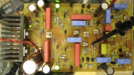
Here's the latest edition of the AIO board in for some gain-phase measurements. All stages in this version use feedback of some sort. Schematics will follow when the gain-phase is sorted out. This boars also incorporates some things I've learned in my discrete regulator thread in the analog source section.
Attachments
I finally got the gain-phase aspects of this preamp sorted out. The presence of cascode stages in two of the gain cells I'm using made compensation a bit more difficult, but I now have some compensation schemes that work.
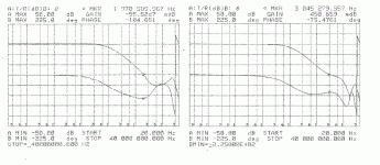
Attached are the gain-phase plots for the two halves of the RIAA preamp. The input stage is shown on the left, and the output stage on the right. Note that these are each the responses of the individual gain blocks, not the RIAA preamp as a whole. The markers on each plot are set at the 0dB crossover frequency (as near as I could manage). Zero dB and zero phase shift are both on the exact center line of the plots.
Both gain blocks have good phase margin. The input gain block (left side) has less gain margin than I would like, but I'm going to proceed to listening tests, as I'm getting impatient to hear this thing. I don't know how much I can trust the readings at the far right of the plots anyway, as I'm scanning all the way out to 40 MHz and may need a better setup to accurately see what's going on out there. With that in mind, I'm going to try and scare up some SMB to BNC adapters tomorrow. A straight cable connection might yield better results than the BNC -to- easy hook cables I'm using now.
Attachments
Last edited:
- Status
- This old topic is closed. If you want to reopen this topic, contact a moderator using the "Report Post" button.
- Home
- Source & Line
- Analog Line Level
- All-In-One Preamp Circuit
