Thanks wahab
I understand, now Alex came up with such a nice PC board design I will see if I keep going ahead to fabricate my own (design) PC boars or wait if it will be enough interest to org. a group buy.
Of course it would be great to test the amp before, so those who interested to have some idea sound wise, $$$ (investment), reliability etc. Not because I have second thoughts!!!
Looking at the sim result these amp outperform the famous GM.
No need for special or hard to find parts..
Even that would be a plus to take these amp serious by those who like the mosfet sound and these design!
Before all Hitachi mosfet will disappear from the market aldo Exicon laterals are great to. Just as a back up!
I'll go with Hitachi.
By the way to test the amp it would be great if not just me some other experienced DIY-er would test it to..
Greetings Gabor
Last edited:
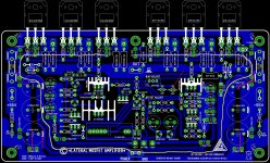
New PCB rev4.2 layout acording to last posted schematic")
Regards Alex.
Hi Alex , Q20 also need a heatsink...
In fact Q7 1.2W dissipation is now shared 50/50 with Q20 ,
for 0.6W each , so it s either two small heatspreaders or a bigger
common one.
Also , in parralel with the bias trimmer you did implement two Leds
in serial while it is a led and a normal diode , although one can simply
put a standed up diode instead.
Anyway , thank you for the design , no doubt it will be much helpfull
for people willing to give this amp a try.
Hi Gabor
Indeed , if one has the mosfets i think it s smarter to build this one
rather than the GM even on a cost basis.
There s quite a large panel of adequate components , cheap parts
can be used as well in straight replacements , so the cost is mainly
dependent of the power supply requirements and to a lesser extent
of the laterals.
Of course , the PCB cost is highly variable from negligible with self etched board
to consequent for professionaly made ones.
board lines does look somehow neater now, absolutely
is there a special reason why you split the ground lines for supply caps into multiple thin lines ?
any board measurements ?
(to see how it fits the heatsink)
edit, btw, since the output transistors legs are mounted from below board(I suppose), it would be easy let the board cover a bit of them, to make room for a wider power supply line there, at board edge
About the layout
1)If we use the 6PC 100uF caps at the power mosfet the ground trace almost close the whole circuit like a circle...
2)At the bias trimmer one is a LED one is diode Red Arrow
Do we need 3PC 1000uF caps on the PC board each side? Or 3PC 100uF for the higher voltage..
I think 2PC more than enough.
As power supp capacitance not enough and for coupling caps overkill
If we use only 2PC we can leave a bit more room (purple)between the HC voltage and Ground..
Yellow line almost a circle???
I learned the ground has to be like a glows or a tree. If I'm wrong please forget it!
I know how hard to lay out a good PC board and thanks to Alex he is very patient, helpful, gifted and talented!!!
Just a few thoughts..
Greetings Gabor
1)If we use the 6PC 100uF caps at the power mosfet the ground trace almost close the whole circuit like a circle...
2)At the bias trimmer one is a LED one is diode Red Arrow
Do we need 3PC 1000uF caps on the PC board each side? Or 3PC 100uF for the higher voltage..
I think 2PC more than enough.
As power supp capacitance not enough and for coupling caps overkill
If we use only 2PC we can leave a bit more room (purple)between the HC voltage and Ground..
Yellow line almost a circle???
I learned the ground has to be like a glows or a tree.
If I'm wrong please forget it!I know how hard to lay out a good PC board and thanks to Alex he is very patient, helpful, gifted and talented!!!
Just a few thoughts..
Greetings Gabor
Attachments
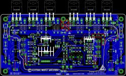
These is the best design Alex came up.
That is the reason I ad some marks because these is very close.
If I remember well the R17/R18 has to be 2W type if not please forgive me.
We could spread a bit the leads of the mosfets, that I say because we mount the mosfets from the bottom (copper side).
If the trace to small very easy to damage the PC board in case if we need to desolder etc the mosfets.
Tinitus you right about that!
The PC boards size is there 189X93mm
wahab do we need those 6PC 100uF caps at each mosfet?
That ground trace bugging me a lot!
Greetings Gabor
Attachments
I would quit the big onboard supply caps
better to place seperate big high current supply caps close to board
and instead have bigger supply caps for the higher voltage frontend
but I guess it could be argued
I agree with you!
2X470uF is more than enough for high power on the board
2X100uF for the higher voltage
Even one each would be good but let s leave room who likes higher uF.. 2x470 or 1x1000uF etc but no under circumstances 3X1000uF..
That over kill for coupling caps and for PS is not enough..
Greetings Gabor
R17/18 dissipate at most 0.05W each so 0.5W resistors could be enough
but they have to withstand the power on charging current wich can be
quite high if capacitors values are about 1000uF.
With 220uF they should be enough.
As for the 6 mosfets caps , well , they do no bad but perhaps 0.22uF MKP
would be more relevant given that there is already electrolytics filtering caps
in the PCB for theses rails.
Wahab, why don't you use easy voltage for both front and output stage? 55V for both, and I will finish building the amp within 3 days.
Jay feel free to do that, It will be good that way to.
It has a lot of advantage for the separate PS. Many designer (in high end amps) use regulated PS for the front and higher voltage.
You know better that then me!
That was my will (regulated front PS) but I'm happy these way to.
You can wind on your toroid 2X3.5m wire..
Or just use a resister to connect the front with 55V..
Greetings Gabor
.......Guys do you mind if donpetru post his creation here or keep these thread for the Hitachi laterals?.......
Donpetru's variation is an offshoot of this design. So it should stay here as it will be compared with the original circuit. I don't see any harm in his circuit being here and actually think it's better here for evaluating differences.
I don't see how the hexfet's can 'sound' any better but it would be interesting to keep the progress and results within this thread . We would want comparative listening tests . Without that all of this will just be a theoretical exercise. It does make the thread even more interesting !
Jay feel free to do that, It will be good that way to. It has a lot of advantage for the separate PS. Many designer (in high end amps) use regulated PS for the front and higher voltage.
It is just curiosity. About the cascoded VAS. I don't want to design my own amp, I want to listen Wahab's amplifier and to have a proof if I'm right or wrong.
I don't see how the hexfet's can 'sound' any better but it would be interesting to keep the progress and results within this thread . We would want comparative listening tests . Without that all of this will just be a theoretical exercise. It does make the thread even more interesting !
Agree about the HEXFET version here. And agree that it cannot sound any better. In simulators anyhow, they may be better (IRF240/9240, IRF632/9630).
Reference "The amplifier was designed by Paul Kemble (head of NAIM company)... ...Here is the website of Paul K. A Paul Kemble web page - Hitachi Fet designs." I would appreciate it being noted that I did not design this amplifier and have never worked for Naim although I am the author of the Angelfire and Tripod sites bearing my name.
Hope this helps.
Hope this helps.

Alex the Zobel N is repeated, U added twice to the circuit..
Greetings gabor
I just have to ask.
What PCB-software is this board made in?
I have usually built my electronics fully manually, but see the benefits of using a good PCB-software. I have tried the ExpressPCB software, but needs some advice of where to find the manufacturer with the best price/quality value.
Sorry for the OT here.
Double sorry, It's Alex I should have asked.
- Home
- Amplifiers
- Solid State
- All Hitachi Lateral Fet amplifier for DIY described by Paul Kemble