• Member Blogs have been stealth lauched / soft launched. Members who are keen to start a useful informative blog and who will keep it current can contact GerardV to be set up. Blogs that go stale will be archived.

Aliexpress "20W" dual output DC-DC converter module

DC-DC_20230727152813.png


This is a handy and affordable little dual-polarity output module that's available on Aliexpress here for about $5. I
should point out that I bought mine on Taobao but the modules look to me to be identical whichever platform you
happen find them on.

I fired this up and made a few measurements, primarily I started off looking at its efficiency. The quiescent is
decently low (10mA or so) but delivering around 4W of output at +/-24V I found the efficiency rather dismal
for a switcher and definitely lower than as advertised on the vendor's Ali page. I was getting about 55% which
meant around 4W was going somewhere - initially I wasn't sure just where. I figured best to wait a while and
then poke around with my finger to see what was getting hot as 4W wouldn't be possible to hide for very long.

It took less than a minute to detect that the toroidal inductors were to blame, everything else was cool. After
extracting them and taking the shrink jacket off one, it looks like this :

toroid_20230727154036.png


My LCR meter confirms a nice low DCR but at 100kHz, the resistance is close to 3ohm indicating
high AC losses. The switching chip operates at 180kHz so obviously this particular material isn't a
great choice in this application. From its colour scheme (yellow/white) its probably a type 26
which is about the cheapest toroid going, a great choice for a CLCLC power supply filter but
unsuitable for high frequency work. I have quite a few different sizes of Sendust cores so why not
try some of those, they're much better at HF.

Before that though I wanted to see if I could understand the schematic, a switcher with 3
inductors isn't something I've encountered before.

SEPIC_sch_20230727161427.png
 
Last edited:
  • Like
Reactions: 1 users
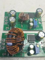
Here's the result - 3 separate type 26 toroids replaced with 1 trifilar wound sendust toroid. Efficiency figures to follow.

trifilar_sendust_20230727181301.jpg


The trifilar wire is made out of 3 strands of 0.29mm enamelled copper, I unwound about 2m and divided that into 3, tied one end of the three parallel strands together in a knot then closed the chuck of my hand winding machine around that and turned the handle whilst holding the other end taut. The tricky part is then figuring out which strand pairs up with itself at the other end, different coloured magnet wire would come in very useful.
 
Last edited:
  • Like
Reactions: 1 user
I arranged an array of resistors to draw symmetrical current (between + and - outputs, no current to GND). At +/-24V output with a load of 94mA I get 350mA drawn at 15V supply.
Thus input power is 5.25W and output is 4.53W giving an efficiency of 86%. That's more like it. This number degrades to 85% at 10V and 20V input. The toroid gets ever-so-slightly warm so I'm guessing that's where much of the 0.72W wasted is going.

The seller's page says that just using the -ve output isn't allowed so next I'm going to see what happens with an asymmetrical load. Many of my DAC chips draw more power (a factor of 2 or more) from the negative rail than the positive so an asymmetric load has to at least work.
 
  • Like
Reactions: 1 user
With asymmetrical load the first thing that jumps out is the -ve supply doesn't have as good load regulation as the +ve one. With symmetrical load the load regulation looked excellent.

I set up a load fairly representative of an array of DAC chips, nominally +/-7.5V out. Positive supply load 0.6W, negative 1.4W, total 2W. At 10V in, 230mA -> efficiency 87%; at 20V in, 120mA -> efficiency 83%. The -ve supply runs about 70mV lower than the positive one.

Next - just loading the -ve supply.

Before I get on to the above, here's a quick comparison between sendust cores. The original one is 14mm dia, the one in front is 23mm. Efficiency of the bigger core is slightly better - 10V in, 225mA; 20V in, 115mA. So around 89% best case. Probably its the copper losses which are lower as the larger core allows thicker wire.

Two_sendust_20230730171831.jpg

With just the -ve supply loaded, the output voltage droops - from 7.5V down to 7.1V. Still quite usable if there's a post-regulator with enough drop-out headroom.

Next up - another dual output board using a different chip.
 
Last edited:
  • Like
Reactions: 3 users
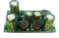
Over on Aliexpress, this next module is called 'DD1912PA' and goes for $2.72 right here. Oddly, its
also available on a Taobao page which is almost entirely written in English. Makes me think 'foreigner
pricing':devilish:

XL6007_20230730195012.png

Its about half the PCB area of the earlier one and uses XL6007 which runs at 400kHz (vs 180kHz for
the XL6019). The power output is claimed to be 8W, I haven't tried that much loading yet.

What's different about this one is its using 3 ferrite cored inductors. So no need to change those for
upping the efficiency, ferrite is even lower loss than sendust typically. Why I object to these particular
inductors has nothing to do with the core material and everything to do with the topology. They're bobbin
wound which for the uninitiated means unscreened. You won't want to put this board anywhere near
sensitive stuff so as not to expose that to magnetic flux lines at 400kHz. So on the basis of making
this board a team player we need a screened inductor solution for it.

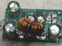
DD1912PA_20230730200152.jpg
Same 14mm sendust core but based on the efficiency comparison earlier I've gone for thicker wire this
time, 0.33mm.
 
  • Like
Reactions: 1 user
I eventually put these SEPIC power supply modules on the back burner because I ran into an issue - startup current.

My bench power supply's highest current limit is 3A and that's roughly the initial input current for the 20W module. But I wanted to run two modules - when I tried that neither module started up because the input voltage collapsed. I figured 6A start-up was rather excessive and certainly wasn't going to work with a weakish trafo to feed it. My proposed solution at the time was to stagger the startups by using a couple of different time constants on the enable pins but I never got around to try implementing that. I did order some LM393 comparators though.

9 months later I have decided to revisit this and from a quick Google I found that SEPIC converters are hard to stabilize when running in continuous mode which is where they end up if you want substantial current output. This post is an extremely helpful pointer - the reference to Dr. Ridley is also a massive help to anyone who wants to design switching PSUs with the least possible math and with maximum fun factor. (me, for one!) Here is a Dr. Ridley video on buck converter design which I highly recommend (I'm only halfway through it myself but its far and away the most helpful design resource on PSU design I've come across on YT) : https://ridleyengineering.com/videos-e/303-power-supply-design-essentials-webinar.html. (I'm linking to his site rather than the YT channel as he also has downloads to support the design process).
 
  • Like
Reactions: 1 user