If the UGS5 module is used for a preamp would loading the outputs to each psurail by 10K or so provide enough dc stability?
Or would it perhaps be recomended to utilise the same method for dc stability as in the older XA amps/ugs modules ("Macmillan resistors").
Or is a servo necessary to correct for common/diff ofsett.
Or would it perhaps be recomended to utilise the same method for dc stability as in the older XA amps/ugs modules ("Macmillan resistors").
Or is a servo necessary to correct for common/diff ofsett.
I recently built a UGS based preamp that used 10K resistors to the rails instead of the single resistor to ground as a nominal load on the output. It worked fine. It's very DC stable and sounds wonderful. I also used 22K MacMillan resistors. I am planning on removing these when I get the chance to see how the DC and sonic performance is affected.
The UGS is the usual deal with 389/109 type inputs followed by current mirrors.
Graeme
The UGS is the usual deal with 389/109 type inputs followed by current mirrors.
Graeme
Is it allowed to use a single transformer with two separate equal secondary windings and two bridge rectifiers soldered in?
Let me know if this works -- I kept smoking bridges when I tried it, and I never figured out why.
JJ
Hi jupiterjune,
it works perfect! ...no smoking bridges...
Have a look in the F4 manual - it uses the same dual bridge rectifier constellation.
No idea what you have done wrong...
...perhaps very oversized transformer with to small diodes?
...short circuit?
...wrong connected bridges?
Check your complete connections!
Take comfort, a rectifier is a cheap thing....")
Dirk
it works perfect! ...no smoking bridges...
Have a look in the F4 manual - it uses the same dual bridge rectifier constellation.
No idea what you have done wrong...
...perhaps very oversized transformer with to small diodes?
...short circuit?
...wrong connected bridges?
Check your complete connections!
Take comfort, a rectifier is a cheap thing....
Dirk
Hi Tazzz,
at the moment I can't give you a good hint.
Have built the UGS5 and have to find some things out.
The first constellation I tested was a preamp connection (input, output, feedback resistors and coupling caps) added by 10k output resistors to ground and without the Macmillan resistors (the modul doesn't offer a source connection to outside). But this way does not give enough DC stability. The measured differential offset is very small (only a few mV) but absolute offset fluktuates to much.
The next days I will try to load the outputs with the VBG (described above) which will offer a divider network between the supply rails and output. Hope that this will stabilize the system...
When the results will be good I let it know...
(I could imagine that the new preamps will also use this modul + IC potentiometer + differential stage for SE-output...)
Dirk
Hello to all!
Some news from me...
Have done some experiments at the weekend with the new UGS modul + voltage bias circuit + a follower pair on each side + SE resistors (output to V-)
The results are quite good and I cannot believe what I have meassured...
...becoming a bit euphoric...
The used voltage bias circuit is made of the TL431 with the standard resistor/trim network biased by 10k resistors from each supply rail (+/-24V). To drive it in the middle as Mr. Pass has told, I use a voltage divider (two 10k resistors) and bypass each resistor with an 220µF elcap. Offset was meassured with shorted inputs to ground. Gain was meassured with 1kHz sine wave generated by the computer given to one input - other input grounded.
The output bias current was set to 500mA for the n-device and 50mA for the SE-resistor (480R) leaving 450mA for the p-device. Gain was fixed with feedback to approx. 26dB.
Also I use input to ground resistors (15k) (virtual ground to ground).
I came to the following results: Absolute offset is low – something between -75mV and -20mV, differential offset is extremly low – 1,5mV to 0,2mV!! Clipping is absolute symmetrical.
More interesting is the fact that a reduction of current bias to 75mA for the n-ch (25mA p-ch, 50mA SE-resistor) only drop down both outputs to -200mV. So it should be no problem to reduce the voltage bias for the stand by without getting to much unhandsome abs. offset.
But there are some things which confuse me a bit:
The meassured open loop gain is approx. 57dB with 15k input resistors + 15k virtual ground to ground resistors. That’s a bit to much – results in 31dB feedback...
Are there more possibilities than the input-ground resistors to reduce it, and to which value am I allowed to reduce this resistors?
The second thing are the outputs of the front end: It seems that they are not very stable (although the follower outputs are) – is that a problem and does it help to use a resistor to ground?
Last point are the abs. and diff. offset trimmers. The influence is very very high. I have to leave them in the middle position and turn them only for a fraction of a millimeter for the right trim.
It would give me great pleasure, when you Mr. Pass can give me some feedback if I am on the right track.
Best Regards and sorry for the spelling mistakes...
Dirk
Thanks!!!
Thought that I have to scale the pots, too - but had calculated that for example a 10° turn on the abs. pot would change the current through the n-common source devices only for about 0,7mA (using 1,5kOhm resistors to load the cascoded jfets, a 500R trim pot for absolute offset and a 1k pot for differential (meens with both pots in middle position a 2k load for each jfet) and 220R loads for the mosfets).
I'm not sure if the UGS output is really stable enough and as a result to sensitive to trim it. Hmmmm.........
Stupid question, but what is meant by degeneration (the translator tells me "feedback", which makes no sence). Is degeneration done by reducing the virtual GND - GND resistors?
Dirk
Hi!
You are right! For more clearness what we are talking about it is time to publish a schematic.
The shown circuit is not the ready amplifier, it is only my testcircuit without a stand by function, thermistor compensation and the complete output stage with ten parallel mosfets.
My choosen bias current is 500mA through the n-device which is doubble the current I would take for each with 10 parallel fets.
Perhaps again a short explanation to my trim pot problem:
The 1k differential pot works perfect. I can adjust the differential offset between +0,9V and -0,9V over the load. This should be the optimal range for it.
The 500R absolute pot makes the trouble. To get a symmetric behave in the middle position of both, you have to take half the value for the abs. as for the diff. pot. But with this value the absolute offset rises to +/- 10V with full turn of the trim pot and this makes it difficult to adust the offset very close to 0V.
Some ideas?
Regards
Dirk
Attachments
Call me Dirk....
Not really "noisefree" tonight. Have drunken to much redwine! ;-)
There are a lot of possibilies where to put in the trim pots.
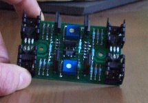
The UGS module is ready so I don't wanne change the layout again.
The only thing what I can do in my situation is to raise the values of the jfet loading resistors on the negativ half and reduce the value of the abs. trim pot. But as I meant before, I do not know if the problem is really the pot size itself. When my eyes are good enough I have seen four equal values for the loading resistors on the original.
It is not a problem to use other values - it is more that I need an explanation why the pot is so sensitive.
Here is a photo of the ready module. Resolution is bad - very old digital camera...
Regards
Dirk
Not really "noisefree" tonight. Have drunken to much redwine! ;-)
There are a lot of possibilies where to put in the trim pots.
The UGS module is ready so I don't wanne change the layout again.
The only thing what I can do in my situation is to raise the values of the jfet loading resistors on the negativ half and reduce the value of the abs. trim pot. But as I meant before, I do not know if the problem is really the pot size itself. When my eyes are good enough I have seen four equal values for the loading resistors on the original.
It is not a problem to use other values - it is more that I need an explanation why the pot is so sensitive.
Here is a photo of the ready module. Resolution is bad - very old digital camera...
Regards
Dirk
Attachments
Hi dirk
First for AC The Positive side sees 2K on the collectors the negative side sees 1k5 at the collectors.
Then assume a total of 10ma running.
The adjustment range is from 7.5v to 12.5 volt.
Find out how much you need and change the resistors R4 R5 and the pot P2.
Another solution is to put also 2K in the negative side and P2 50 Ohm and ad a 22 Ohm resistor above P1.
Or make P1 P2 50 Ohm and all four resistors 1k5.
Your module is very nice but it was better to build a proto first
Rob
noisefree said:
The meassured open loop gain is approx. 57dB with 15k input resistors + 15k virtual ground to ground resistors. That’s a bit to much – results in 31dB feedback...
Are there more possibilities than the input-ground resistors to reduce it, and to which value am I allowed to reduce this resistors?
Good to hear you are making progress.
The UGS is essentially a transconductance amplifier and there are not too many ways of changing the open loop voltage gain if the current gain of the ‘mirror’ is required to be a fixed value (a typical value for the latter being about 4). The most obvious control is the output resistor to ground (or power supplies) but reducing this too far will draw too much current from the module. The only other way to my knowledge is to add source resistors to the diff pair (Rs1 – Rs4 in post 1651). This reduces the gain through local feedback or “degeneration”.
I’m not sure how much influence on open loop gain the resistor from virtual earth point to ground has although it will obviously reduce the overall gain by acting as a potential divider with the input series resistor.
Why do you wish to reduce the open loop gain?
Ian.
Ian Macmillan said:I’m not sure how much influence on open loop gain the resistor from virtual earth point to ground has although it will obviously reduce the overall gain by acting as a potential divider with the input series resistor.
It's a good way to "throw away feedback". While the SuperSymmetric
circuit does a good job of improving performance with low amounts
of feedback, it is sensitive to excessive open loop. Resistors to
ground from the summing junctions of the input not only allow
easy control of that, but make the circuit less sensitive to source
impedances.
Thanks Nelson. I think I understand the effect but I will have to "play" with some values in a real circuit and observe the change before I understand the precise impact.
Dirk: sounds like you need to reduce your resistors and measure the change. I don't think you need worry too much about going too low.
Ian.
Dirk: sounds like you need to reduce your resistors and measure the change. I don't think you need worry too much about going too low.
Ian.
I should learn to think more carefully before I reply as there is clearly more complication in the detail than I had assumed. Perhaps Nelson will be good enough to help me out.
In principle I would have thought that “throwing away” feedback would normally increase the closed loop gain of an amplifier given that feedback is generally negative, i.e. less feedback results in more gain, at least until the open loop figure is reached. The effect of a resistor from summing junction to ground must therefore be subtly different.
I’m also missing how such a resistor effects the open loop gain of the amplifier but perhaps this depends on how one defines/measure the latter. I usually define open loop gain as that of an amplifier with its feedback removed, i.e. no resistor from output to input in this case. A resistor from summing junction to ground doesn’t change the amplification factor in this case although it will reduce the overall gain as measured from the input (this being the other side of the series resistor connected to the summing junction) through potential divider action. Is this what was meant by open loop gain in this context?
So what is going on in the case of the AX? The only theory I can come up with goes like this (and is probably completely wrong). The action of the resistor from summing junction to ground works in two ways. First it reduces the feedback factor (by “throwing it away” or attenuating to ground). By itself this would increase closed loop gain except that the resistor also attenuates the input signal through the action of the potential divider it creates with the input series resistor. The net effect is therefore less overall feedback and lower closed loop gain.
The advantage? I’ll hazard a guess that it is the amount of overall feedback rather than open loop gain per se that supersymmetry is sensitive to, hence reducing the feedback in this way also improves its performance.
Am I close or do I have it completely wrong?
Ian.
My new job has given me new contacts at R-Theta. A new Group Buy with lower pricing is possible. I will be buying some extrusion to put my Aelphx back on track.
I have started a new thread in Group Buys if your interested.
Now back to your regularly scheduled programming.
Anthony
I have started a new thread in Group Buys if your interested.
Now back to your regularly scheduled programming.
Anthony
I'll give it a try.
Assuming we remove the feedback resistors.
The 2 resistors from the summing junction to ground, together with the input resistors, form an attenuator even in open loop. Maybe you're not throwing away much, but you do throw away something. If I am not wrong, you throw away more when the loop is closed.
Treat one half of the AX as an "opamp", put the +input to ground, add the input resistor, the grounding resistor, and the feedback resistor to the inverting input, and work out the close loop gain, etc. The effect of the grounding resistor should perhaps then be more obvious.
(Yes, I did this maths a while back, as I did not quite understand the performance penalties of the AX with single ended input signals.)
Patrick
- Home
- Amplifiers
- Pass Labs
- Aleph-X builder's thread.