Hi acaudio,
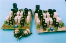
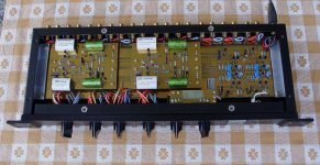
that P1.7 really looks great!! Very professional to me. I wish my diy circuits would look as good as yours from the inside.
Have you ever thought of a remote control?
What is on the double decker boards beneath the main boards?
Would you mind sharing their layouts (or did you already?)
Cheers
Thomas
threefff said:Hi acaudio,
that P1.7 really looks great!! Very professional to me. I wish my diy circuits would look as good as yours from the inside.
Have you ever thought of a remote control?
What is on the double decker boards beneath the main boards?
Would you mind sharing their layouts (or did you already?)
Cheers
Thomas
Hi Thomas,
a remote control for volume? Should be doable, look at www.schuro.de
The double deckes boards are at bottom source switch (relay) and on top volume board.
For layouts look here: http://www.diyaudio.com/forums/showthread.php?postid=550815#post550815
Cheers
Adam
threefff said:Hi acaudio,
I really appreciated the layouts you already posted. I didn't find the relay boards.
Cheers
Thomas
www.acaudio.de/rel_control.pdf
/Adam
Hi acaudio,
thank you very much.
Right now I also do understand, why you where pointing to Schuro regarding remote control. The program of the 87C750 is unknown, isn't it?
Somehow the power off values of volume und input selector have to be saved (internal EPROM of the controller?) and represented to the latches at power on, right?
Also: the transmitted code of the remote control is unknown, at least to me.
Any ideas? (Yes, use the ADC Volume control....)
Cheers
Thomas
trouble shoot with your design
http://www.acaudio.de/rel_control.pdf
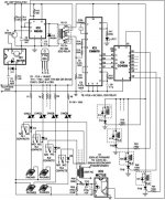
From page 8-10 of your link does not match with your photo such as Relays 1-6 in volume board but in schematic & pcb there are 7 Relays (1-7)
Why don't use pins 17-18 in IC1 (ADC0804) for increase to 256 steps and use CD4013 for breaking POP-NOISE ?
I have some question with IC4 (4028N) How to connect point 12V/S/A/B/C/D and How it control function "ON" to R2, R22 for switch relay coil K1, K2
Thank for your shared idea")
REGARD
AHT
http://www.acaudio.de/rel_control.pdf
From page 8-10 of your link does not match with your photo such as Relays 1-6 in volume board but in schematic & pcb there are 7 Relays (1-7)
Why don't use pins 17-18 in IC1 (ADC0804) for increase to 256 steps and use CD4013 for breaking POP-NOISE ?
I have some question with IC4 (4028N) How to connect point 12V/S/A/B/C/D and How it control function "ON" to R2, R22 for switch relay coil K1, K2
Thank for your shared idea
REGARD
AHT
Attachments
Hi altogether,
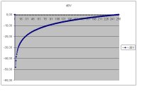
I cought a fever and spend some days in bed. So I had the time figure out the attenuation for each step of the resistor network of the P1.7. See image attached.
From the image it can be seen, why Nelson uses a look up table in the 87C150: only approx. 70 Steps are needed if you want 0,5dB between them (the lowest are fare more aparat, here you find 3 to 4 dB spacing between them).
If you want a curve without jumps (stetig), you need to have your resistors in powers of 2 of the smallest value you are using. The absolute value doesn't care, as long as you are not looking at the input / output impedances of pre and poweramp (what I did here).
With this limitation 8 bit can only code for a attenuation of 48 dB (as 16 bit do for 96 dB on our CDs).
Have fun
Thomas
Attachments
Re: trouble shoot with your design
Hello,
the relay board´s are newer, with 7 Relays (for next projects). I use at present only 6 of them.
Using of full range (256 bit) has only ~19mV between the steps, this can be unstable. You can try it .
I use a binary switch for source select, 12V at common, ABCD binary, "S" is contact between the steps, the ON function turn the preamp on if any source is selected. No source selected => Preamp off.
R2/C2 and R22/C13 do a little delay.
Greetings
Adam
aht said:http://www.acaudio.de/rel_control.pdf
From page 8-10 of your link does not match with your photo such as Relays 1-6 in volume board but in schematic & pcb there are 7 Relays (1-7)
Why don't use pins 17-18 in IC1 (ADC0804) for increase to 256 steps and use CD4013 for breaking POP-NOISE ?
I have some question with IC4 (4028N) How to connect point 12V/S/A/B/C/D and How it control function "ON" to R2, R22 for switch relay coil K1, K2
Thank for your shared idea
REGARD
AHT
Hello,
the relay board´s are newer, with 7 Relays (for next projects). I use at present only 6 of them.
Using of full range (256 bit) has only ~19mV between the steps, this can be unstable. You can try it .
I use a binary switch for source select, 12V at common, ABCD binary, "S" is contact between the steps, the ON function turn the preamp on if any source is selected. No source selected => Preamp off.
R2/C2 and R22/C13 do a little delay.
Greetings
Adam
Hello,
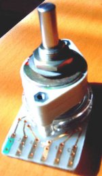
the switch is a ordinary binary switch. Type EBE 46-353.
Pins: 1(S), 2=2^0, 4=2^1, 8=2^2, 16=2^3. (habituation-needily...)
This switch has 16 Steps. In my pre I use only 5 (off + 4 sources) mechanical fixed inside. Pin 1 gives a signal only between steps, this can be usually used for enable/disable selection, I use them, but this can be disconnected, no difference in function. It prevents that the preamp goes off between steps by (very) slow turn.
The same switches are used as gain pots.
This is all, no magic.
Adam
âËÂ...áÅéǼÁ¨ÐËÒ¨Ò¡ä˹ÅèСêÒº...ÍÔÍÔÍÔ...½ÃÑè§ÍèÒ¹äÁèÍÍ¡
âËÂ...áÅéǼÁ¨ÐËÒ¨Ò¡ä˹ÅèСêÒº...ÍÔÍÔÍÔ...½ÃÑè§ÍèÒ¹äÁèÍÍ¡
This mean where can I buy this switch ?
I think I maybe have to modify function "ON" and selector A/B/C/D to manual switch
Thank for your quickly reply
Do you like Threshold fet-10HL ?
I cloning PCB & Schematic now it use J-fet differential input and complementary transistor output
Could you agree with me to make a project same p1.7/ksa50/alephx/blz/...?
Attachments
Re: âËÂ...áÅéǼÁ¨ÐËÒ¨Ò¡ä˹ÅèСêÒº...ÍÔÍÔÍÔ...½ÃÑè§ÍèÒ¹äÁèÍÍ¡
Have a look at:
http://www.ebe-gmbh.de
Keep it up !
Best wishes
Adam
aht said:...This mean where can I buy this switch ?
Have a look at:
http://www.ebe-gmbh.de
aht said:...Do you like Threshold fet-10HL ?
I cloning PCB & Schematic now it use J-fet differential input and complementary transistor output
Could you agree with me to make a project same p1.7/ksa50/alephx/blz/...?
Keep it up !
Best wishes
Adam
- Status
- This old topic is closed. If you want to reopen this topic, contact a moderator using the "Report Post" button.
- Home
- Amplifiers
- Pass Labs
- Aleph P1.7 first pictures