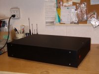
I am surprised to see that you have so many leads sticking out of the bottom of your board. Why don't you cut them off? If you don't, they might short out to the case once you have everything closed up.mjounot said:I finally have my ONO assembled . . .
I had a brief listen and it sounds good.
Iwill attempt to post photos.
What do you think guys?
Mike
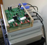
Here's a picture of my ONO, which I built in two boxes - one for the power supply (single toroid, dual power supply boards) and one for the phono stage.
---Gary
Attachments
I haven't seen Pquadrat online recently, but I know some other people have asked him the same question and the answer he gave them was no. Perhaps Bouke "Bakmeel" has some left? He also designed Ono boards separately from Pquadrat.
Good luck
Groeten,
Jarno.
(still busy finishing up my Ono boards, powersupply is up and running)
Good luck
Groeten,
Jarno.
(still busy finishing up my Ono boards, powersupply is up and running)
Ono PCB's
I have have the drawings for a single side PCB from Kostas A. Vazakas as published on the passdiy gallery.
If anyone is interested let me know and I will digg up the drawings.
Also when there is enough demand, I will be happy to order these boards in a group buy.
These boards work fine - I've build both the ono from Peters boards as well as the ono from Kostas's boards.
These days, I'm doing some indeep measurements of my ONO preamp, or should I say XONO since I'm using a full dual mono with separate power supply.
Check this thread for interesting results very close to the published Passlabs specs.
http://www.diyaudio.com/forums/showthread.php?s=&postid=1010167#post1010167
Check this thread for interesting results very close to the published Passlabs specs.
http://www.diyaudio.com/forums/showthread.php?s=&postid=1010167#post1010167
Yeah, time flies.
I'm putting together my system, in nice cases and so on, and found time to do some tests in my ono. My problem was that the R25 pot was not able to bias enough the output mosfets (IRF610 are from Harris), so I reduced the R53 value to 100 Ohm. Is there any problem on increasing the bias current that way? should I also increase the bias at R67?
I'm putting together my system, in nice cases and so on, and found time to do some tests in my ono. My problem was that the R25 pot was not able to bias enough the output mosfets (IRF610 are from Harris), so I reduced the R53 value to 100 Ohm. Is there any problem on increasing the bias current that way? should I also increase the bias at R67?
Just in case it's helpful for someone, the diodes that work best are the red ones, but the ones that are transparent when are not biased.
I changed the diode, but couldn't bias the output stage enough. I'm using Harris instead of IR, could this be the reason? Maybe the harris part needs higher Vgs?
I changed the diode, but couldn't bias the output stage enough. I'm using Harris instead of IR, could this be the reason? Maybe the harris part needs higher Vgs?
Those volt readings are fine, actually I managed to get the complete Ono (MM and MC) to work properly again. In fact, now I'm able to get much higher biasing. I think it's due to the slightly higher rails I'm using (32V).
I had almost a week of semiconductor failures (due to other semis failures in chain) that almost got me crazy, but finally I understand the circuit (I think).
I'm opening a new thred to discuss the ono scheme, to learn and to be able to check that my ono is 100% performer. For example, I get more Vgs value in the 9610 part than the 610 part. Now I'm not at home for one week, but I maybe have time to open the thread.
Ono C39
Hello,
I'm new to this board, but it seems my question has not been posed yet.
I started to build an Ono clone recently. In the schematic C39 is labeled with a value .001. Below the schematic is written "C39 .01PP ECO". As far as I could find out all part lists of DIY projects on the web use a 1 nF capacitor. In the placement it looks as if a bigger part is used in later revisions.
Was there maybe a change in the parts list? What does the acronym ECO mean?
Greetings,
Chris
I don't know the meaning of "C39 .01 ECO..." and I don't know if is concerning the capacitor C39, because its value is 0.001uF and not 0.01 uF. In my list of materila is indicated a capacitor of 1nF of WIMA FKP2 2,5%.
I bought a Polystyrene cap from RS components (item 113-320).
Write my an e-mail if you want to compare your list with mine.
bye Gubino
I bought a Polystyrene cap from RS components (item 113-320).
Write my an e-mail if you want to compare your list with mine.
bye Gubino
- Status
- This old topic is closed. If you want to reopen this topic, contact a moderator using the "Report Post" button.
- Home
- Amplifiers
- Pass Labs
- Aleph Ono Project (from PCB group buy)