
PCBs
I got some more requests for boards the last weeks, so I may organize a collective order for them. Jens had my Ono to listen to it, and he said that it works fine, but may need some refinement on the power supply. Maybe Jens can contribute with his improved power supply ?
So please email me if You are interested in a pair of PCBs. This is only to see if there is enogh interest for it, and for estimating the costs. Boards would be double sided,
with solder stop print and parts position print. Plated throu holes, professional made. I am able to take paypal payments.
If there is interest in at least 20 boards (10 sets), it would take three weeks after payment for production, and then I would ship. This order would be for the Ono boards only.
Peter
Yeah, I enjoyed every minute when I listen Peter’s Ono! His layout is exceptional good and the PCBs are professional made. As Peter said, I heard some hum, but only when the volume control was completely open. His Ono was powered by one, but external PSU. I believe the Ono benefits from independent (L/R) external PSUs and I recommend even to increase the filter capacity (I have in mine 80mF in each channel).
Hi everyone!
Iam just in the process of designing the PCB artwork for the Ono/Xono phono preamp.It will have almost the same physical layout as the original Xono( one big Pc board for the main amplification stages with filtering and regulation-~30cm * 40cm-.and the other for rectification and first stage filtering ~30cm*20cm.)When i finish the Artwork and crosscheck it ,i will release a Gerber file so that everyone can use it (this will take probably a week or so).
Here are my questions:On the picture in the Xono manual there is an electrolytic cap labelled C28 220uF/16V,probably bypassed with C29 47 nF in the position where on the Ono pcb is the coupling cap C10.Can it be that this is the coupling cap between MC and MM stage?!,why electrolyt,why so big (220uF)?Any ideas?
The second question is:my Pcb artwork will have the same crosshatched plane as in the original.Should i ground it,and where ,or should i let it float?(Nelson,Wayne?)
Dragan P.
nagard said:The second question is:my Pcb artwork will have the same crosshatched plane as in the original.Should i ground it,and where ,or should i let it float?(Nelson,Wayne?)
Make the groundplane massive (no crosshatching) and use it as signal ground. Don't forget to make "hot releaf" pads. Otherwise it can be very hard to solder, especially the caps!
Wayne/Nelson has crosshatched groundplane because it's cheaper to produce and can also be an advantage when machine soldering. You don't stress the pcb so much when heated.
PCB order
I got 6 inquiries for boards up to now, which is not enough for a production run. But I can quote prices for the PCBs now:
If I get 10 orders, the price will be:
EUR 88,- for 2 Ono channels,
EUR 35 for one power supply board.
If I get 15 orders, the price will be:
EUR 60,- for 2 Ono channels,
EUR 30,- for one power supply board.
All plus shipping. Paypal is ok, please add 3% for the paypal charges.
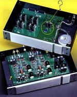
I know, this is not cheap, but the boards are made by a professional PCB manufacturer in top quality. Check the pictures in this thread.
Groundplane will be chrosshatched, like the original. The groundplane is NOT used as a conductor, only connected at a single point to ground.
This is the way I think it works best, and as Pass did it. If You want it different, Your choice, but this design is fixed in this detail.
If there are special requests for component footprints, esp. the coupling capacitors, please let me know, with all details please. I will try to provide proper holes.
The power supply is like the original Ono,
not an improved version. If someone contributes a version with improved regulation (only if successfully build and tested), I can change the board layout.
My Ono is on the way to another member of this forum for review, so You can be sure that the design will work.
Please email me for orders until January 17. Email: peter@hst-netzwerke.de
-Peter
I got 6 inquiries for boards up to now, which is not enough for a production run. But I can quote prices for the PCBs now:
If I get 10 orders, the price will be:
EUR 88,- for 2 Ono channels,
EUR 35 for one power supply board.
If I get 15 orders, the price will be:
EUR 60,- for 2 Ono channels,
EUR 30,- for one power supply board.
All plus shipping. Paypal is ok, please add 3% for the paypal charges.
I know, this is not cheap, but the boards are made by a professional PCB manufacturer in top quality. Check the pictures in this thread.
Groundplane will be chrosshatched, like the original. The groundplane is NOT used as a conductor, only connected at a single point to ground.
This is the way I think it works best, and as Pass did it. If You want it different, Your choice, but this design is fixed in this detail.
If there are special requests for component footprints, esp. the coupling capacitors, please let me know, with all details please. I will try to provide proper holes.
The power supply is like the original Ono,
not an improved version. If someone contributes a version with improved regulation (only if successfully build and tested), I can change the board layout.
My Ono is on the way to another member of this forum for review, so You can be sure that the design will work.
Please email me for orders until January 17. Email: peter@hst-netzwerke.de
-Peter
Thanks perander and Peter!
Somehow I feel more comfortable with Peter's suggestion.I think I will leave two possibilities to connect the crosshatched plane. One at signal input, the other at central power supply ground (of course I will connect only at one point to avoid ground loops, but this way I can test both versions ).
Dragan P.
Let's think big
Peter,
If we would think big: What would be the price if we bring 50 people together ? If I look at the number of requests at the Aleph-X, this has been significantly increased in the last couple of days bringing it up to 800. So, If less than 10% of the people listen to phono, 50 are not unrealistic (if this is OK for you).
Best Regards
nagard said:Thanks perander and Peter!
Somehow I feel more comfortable with Peter's suggestion.I think I will leave two possibilities to connect the crosshatched plane. One at signal input, the other at central power supply ground (of course I will connect only at one point to avoid ground loops, but this way I can test both versions ).
Most industrial pcb's have massive groundplanes and power planes (especially digital ones) just because you want the best posssible ground. It's nothing wrong to have the groundplane as a shield but I think you can get better working conditions with a massive groundplane and use it as a combined signal and power ground. But if your circuit is handling currents (power amp maybe) you must carefully design the traces with currents. For small signal amps it's no problem at all to use a massive groundplane. It doesn't matter so much that you haven't full control over the current paths.
Test equipment
Hi Peter,
early on in this thread you asked about test equipment for measurement of THD, IMD and S/N ratio.
There are a number of instruments which can do these tasks. I personally prefer HP (now Agilent) and Tektronix equipment. On the THD side HP did a series of THD meters, starting with the 333A, then the 334A and finally the 339A. These have progressively lower distortion generators and improved resolution. The 334A and 339A are auto-nulling which makes them considerably easier to use. The 339A is the one to get, though, of course it is the most expensive, with THD resolution down to 0.0018%.
These are all manual instruments and THD will have to be measured at a variety of frequency points to produce a THD/frequency curve.
For reference look at older HP catalogues, or at www.tucker.com (look only, their prices are very expensive!).
HP's later series of digital instruments is the 8903A / 8903B. These do THD, IMD and S/N with resolution down to 0.01% THD. Again you slightly lose some fidelity and resolution, but gain the benefits of automation. To produce THD/frequency curve you need to hook up your computer via a GPIB/HPIB interface.
Tektronix had a line of modular plug-ins, the AA501 distortion analyser and the SG505 signal generator. Both require a mainframe of the TM500 variety, for example, the TM504, TM506A. The SG505 is a particularily clean generator (0.0008%) - the best outside of the Audio Precision gear, I believe. The AA501
module will do THD and has an IMD option (01) though you may have to search for one with this option included. Again these are manual instruments.
There is a later Tektronix series the SG5010 and AA5001 which are digitally controlled - though do not have quite the resolution of the earlier series. These need a different mainframe - the TM5000 series. These modules are very rare and too expensive by comparison to other alternatives but will do THD and IMD.
In my opinion its not worth going for the Tektronix modular family unless you want to use some of the other modules in the series, for example, differential amplifiers, oscilloscopes, pulse or function generators to name a few.
For DIY construction, Erno Borbely published a very interesting IMD measurement design based on some of Cordell's work in Audio Amateur in issues 2 and 3, 1989, see www.audioxpress.com for back issues. This is a complex and expensive multi-board design but will give a wide variety of IMD alternatives.
A more modern approach is to use a dedicated plug in card for a PC. These can be as simple as a standard soundcard (cheap) with appropriate software or can range up to custom designed plug in cards and software, for example, CLIO. These provide probably the best performance for the cost at the moment and all are fully automated.
At the top of the range for audio measurements is the Audio Precision, www.audioprecision.com ,line of products, starting with the System One. These offer state of the art automated measurements of almost every audio parameter but are in the cost no object bracket. Second hand System One examples appear infrequently on ebay.com, typically selling for >$3000.
James
Peranders,
I don't think that a cross-hatched groundplane is necessarily cheaper to manufacture. The same basic stock pcb material used.
Also have you considered that the cross-hatched ground plane might sound better because of lower capacitance while providing similar shielding properties?
Maybe Wayne Colbourne at Pass Labs may be able to answer that question.
Jam
James,
thank You for the in-detail description of the test instruments, I will try to get a HP339A. The 333A and 334A are very old now, but I know that HP instruments from the 80's (like the 339A) are made to last forever.
The 339A should also be perfect for AC messurements like checking the RIAA curve?
And I agree, HP and Tek are first choice for this (except for audioprecision maybe), I prefer Tek on scopes, and HP on other instruments. Have a Tec 475A scope and a HP 3468 voltmeter now, and I am looking for a nice HP signal generator and frequency counter.
-peter
I don't think that a cross-hatched groundplane is necessarily cheaper to manufacture
Actually you do recover more of the etched copper in the manufacturing process and have lower rejects due to board warping both of which can have cost influence. I had to fight like hell to get solid groundplanes on my last design where I needed the low ESR for large currents. The manufacturing people had a cow!
I wonder if groundplanes are really desired for high end audio as they do add a lots of stray capacitance to the circuit and FR-4 is not the best dielectric. I don't see the point to point wiring crowd using coax everywear for shielding which would have much the same rational as a using a groundplane.
Re: I don't think that a cross-hatched groundplane is necessarily cheaper to manufacture
I have noticed that you get better step response if you make a hole under the input transistors and especially the emitters. This is caused by stray capacitance from the emitters down to ground instead of a high impedance path to the current generator.
But seriously, how often is 2-4 pF harmful? Almost never I would say!
SornilltheWhite said:I wonder if groundplanes are really desired for high end audio as they do add a lots of stray capacitance to the circuit
I have noticed that you get better step response if you make a hole under the input transistors and especially the emitters. This is caused by stray capacitance from the emitters down to ground instead of a high impedance path to the current generator.
But seriously, how often is 2-4 pF harmful? Almost never I would say!
Re: But seriously, how often is 2-4 pF harmful
But if you have so sensitive circuits I think it's even more important with groundplane with holes where you must reduce stray caps. In almost every application note over high speed devices they emphasize the importance of decoupling and groundplanes.
SornilltheWhite said:At the summing input for a high speed feedback circuit with all the RFI around now..... more often than you think. All circuits must be designed with RFI in mind. It is a fact of life. Ignor that at your own peril.
But if you have so sensitive circuits I think it's even more important with groundplane with holes where you must reduce stray caps. In almost every application note over high speed devices they emphasize the importance of decoupling and groundplanes.
If ground plane, then ground plane.
I can think of no good reason to use crosshatch on any board.
If you are worried about warping then pour some solid plane on
secondary side as well and use stitching vias in the pour.
With through hole boards a little warping is usually no big deal.
More important with SMT.
Plus hatched planes are usually a manufacturing nightmare.
Many slivers are created which have to be fixed by the CAM
operator and can cause problems with small pieces of resist
becoming dislocated during imaging process.
Solid ground plane is very easy to "cut out" under inductors, etc.
If different capacitance or impedance is required, adjust the
stackup accordingly.
Hi guys!
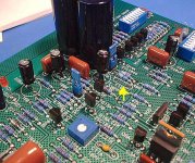
Big ground planes over signal traces definitely raise the stray capacitance, and crosshatched plane has lower capacitance then the same solid ground plane. But does it influence the sound? In Pass designs with highly capacitive MOSFET's and relatively low resistor values probably not too much (and if you design it wisely as Nelson did it in the XA-200 amp you can get rid of the compensation caps, - see the picture below, taken from the Xono manual.)
But it does surely shield more or less the low voltage signals in the Xono.
Look at this picture! It looks like there is no ground plane, neither crosshatched nor solid?
Anyway not on the Pcb borders. And in the PSU unit the two caps and probably the block rectifier for what are they? Can it be that Nelson or Wayne has implemented the Mains DC blocking scheme?
My Pcb manufacturer likes more the solid then the crosshatched version, because with crosshatch he has to be more precise, but of course it does not change the price
Attachments
- Status
- This old topic is closed. If you want to reopen this topic, contact a moderator using the "Report Post" button.
- Home
- Amplifiers
- Pass Labs
- Aleph Ono (nearly) completed