It is going to be an AJ-X eventually, I have only built 2 channels so far. I need to make sure the AJ part works before I move on to the AJ-X.Nice. That an AJ or AJX?
I am in a middle of making a JX board in KiCad based on Peter Daniels FE.
Plan is it will be UMS heatsink compatible solid board for 400mm deep chasis only.
Like on the picture but pcb is a bit wider.
I have a few questions.
How many grounds should board have? Two?
What resistors to use as trim pots? R27 and R8?
Plan is it will be UMS heatsink compatible solid board for 400mm deep chasis only.
Like on the picture but pcb is a bit wider.
I have a few questions.
How many grounds should board have? Two?
What resistors to use as trim pots? R27 and R8?
Attachments
What are prefered resistors for RG? Wirewound or Metal Oxide?
Does their precision mater?
Found Bill Fuss calculations from this thread for RG dissipation.
If I get it right dissipation for 24V rail shoul be like this:
24V/100R x24 = 5.76W
24V/90R x24 = 6.4W
24V/80R x24 = 7.2W
24V/66R x24 = 8.72W
24V/33R x24 = 17.45W
I have a space on board for one RG resistor up to ~35mm or two small up to 5.5mm wide.
So maybe one 100R 7W will do?
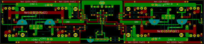
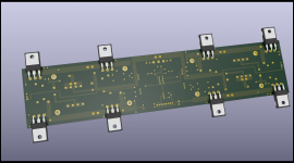
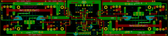
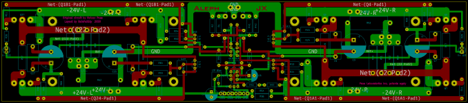
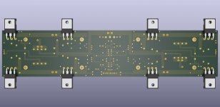
Okay this is my try to layout Aleph JX. Not yet ready but almost.
Left and right side traces are symmetrical as a card except led traces.
Top centre is symmetrical too except Q3-C to Q1B and Q23-C to Q1B.
But both this traces have equal length (32.388mm).
So it is super symmetrical..
I added film coupling caps to electrolyte and ltp css vref is LEDs.
Output resistor to ground is on the board.
Although there art two V+ and two V-, CSS share V+ and V- of both sides.
But one board (channel) should be connected to one PSU anyway.
Thoughts about this layout?
Good, bad, acceptable?
Attachments
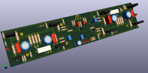
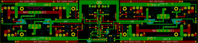
Added text to board, added text to trimmers, made small electrolytic cap smaller, small changes here and there
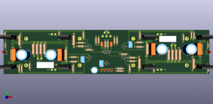
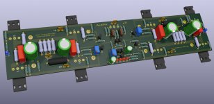
And then I got lazy and start to experiment with 3D.
Found model for FastOn blade, found brown cap that resemble Silmic II, changed color of 3W resistors to resemble Panasonic ERX/ERG, found model to resemble RN/CMF resistors, found silver mica cap model, 7W resistor model changed to wirewound ATE CS6, changed color of 5mm LEDs to blue and fixed all LEDs distance close to pcb.
Also found TO-247 resistor with bended legs. It should be 2.5mm closer to board for hole to fit UMS heatsink but this already start looking beter.
Attachments
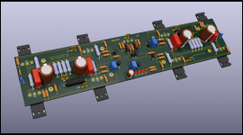
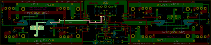
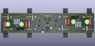
A new effort to improve was made adding DC Servo to my JX layout.
I call it Zen Mod Babelfish JX DC Servo.
I pm'ed Zen to ask if I correctly added it to scheme and after confirmation I now hope I correctly did it in layout.
Long rout to pos out is is bothering me.
Will it work okey like that?
I call it Zen Mod Babelfish JX DC Servo.
I pm'ed Zen to ask if I correctly added it to scheme and after confirmation I now hope I correctly did it in layout.
Long rout to pos out is is bothering me.
Will it work okey like that?
Attachments
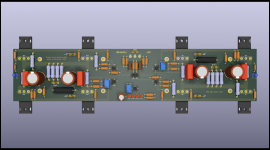
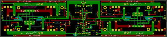
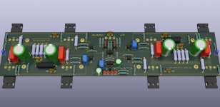
I will continue my monologue posts.
Although it may not look like this but I did countless small changes.
I open project file almost each day and look what can be changed or added.
It might be some kind form of OCD.
Whispering *My precious..* Kidding.
"Aleph JX" text now in a font you might find familiar..
Edit: Reaploaded attachements. Files was too big.
Although it may not look like this but I did countless small changes.
I open project file almost each day and look what can be changed or added.
It might be some kind form of OCD.
Whispering *My precious..*
Kidding."Aleph JX" text now in a font you might find familiar..
Edit: Reaploaded attachements. Files was too big.
Attachments
Last edited:
Can't add mosfets with output resistor to ground stay on the board.
But this should cover all my needs or so I hope.
I also like your approach with external FE boards.
Output stage will always stay intact on heatsink and you can experiment with different front ends easy.
Like with 2SK209 and other variables.
Pretty cool.
But this should cover all my needs or so I hope.
I also like your approach with external FE boards.
Output stage will always stay intact on heatsink and you can experiment with different front ends easy.
Like with 2SK209 and other variables.
Pretty cool.
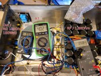
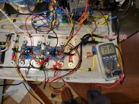
Hello,
I have finished the first channel on Peters Boards after a long construction period.
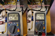
I got a problem RP can only advance up to max O.1 volts with 1.8Kohm resistance.
Do I have to RP 1.2Kohm without modification.
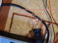
When connecting my XJ boards, the voltage drops sharply and the lamp shines brightly.
I only have one board attached.
I have finished the first channel on Peters Boards after a long construction period.
I got a problem RP can only advance up to max O.1 volts with 1.8Kohm resistance.
Do I have to RP 1.2Kohm without modification.
When connecting my XJ boards, the voltage drops sharply and the lamp shines brightly.
I only have one board attached.
Attachments
Last edited:
Bulb tester is for checking things unloaded, to confirm proper wiring etc., meaning no shorts
when there is no Iq, Bulb Tester is functional and welcome
in very moment circuit is taking some current, there is voltage sag across Bulb, circuit is voltage starved
so, in short - setting circuit and putting it to function - goes without Bulb Tester
when there is no Iq, Bulb Tester is functional and welcome
in very moment circuit is taking some current, there is voltage sag across Bulb, circuit is voltage starved
so, in short - setting circuit and putting it to function - goes without Bulb Tester
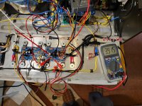
Hello,
I have finished the first channel on Peters Boards after a long construction period.
I got a problem RP I can only advance up to max O.1 volts with 1.8Kohm resistance.
RP changed to 1.2Kohm, no change in the measured voltage.
When connecting my XJ boards, the voltage drops sharply and the lamp shines brightly.
- Home
- Amplifiers
- Pass Labs
- Aleph J-X Amp Project