Oh, by 16,5mA-25mA I was referring to the current through the current source, so in those calculations the current through each JFET would be in the range 8,25mA to 12,5mA. Re-reading the datasheet, I can see the IDSS classification for the BLs (which I'm using) is 6-12mA, so I need to reduce the current.
Oh, by 16,5mA-25mA I was referring to the current through the current source
Sure!
However, it takes not much of an signal to forward bias an 11mA IDSS jfet running at 9mA.
Hannes
So what should I run them at instead? I guess it make sense it run them as low as possible to reduce the heat (and increase long-term stability). The datasheet suggests I shouldn't go under 6mA per JFET. Would 7mA be better in order stay a bit above the lower limit? Any disadvantages with this?
The datasheet suggests I shouldn't go under 6mA per JFET.
Why?
Sure, you can run them lower than that; that's even the general case (just have a look at the original AlephJ).
You can see how close you can bias 'em:
- calculate how much input signal drives amp into clipping
- calculate how much standing current in input differential swings due to this voltage
- add some reserves to be happy camper
- bias input jfets by this amount below IDSS
Lots of additional complications imaginable, like wether you would like to trade current for degeneration (reduces THD) or you might really want to forward bias 'em (be aware of gate current).
It might be easiest to start with a known good value and work from this.
Enjoy! Hannes
Nope.
Resulting thermal resistance number of a blown heatsink depends on the air flow and ; heatsink type, fan, synergy between the two.
A factor three reduction generally requires a substantial air speed, something in the order of >16ft/s.
Which is too high/noisy for audio purposes, a reduction of the natural convection number by half is more realistic for moderate air speed numbers.
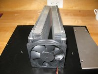
OK, I built my finned forced-air duct and tested it. Using a somewhat crude heat source (a low power ski-waxing iron
") ) and barely audible fan speed I am getting 0.17 C/W from aluminum that should be about .33 C/W. So your prediction was extremely good, Jacco! No worries about fan noise at this airflow. Hopefully each stock Aleph J stereo channel will be happy with this much cooling...
) and barely audible fan speed I am getting 0.17 C/W from aluminum that should be about .33 C/W. So your prediction was extremely good, Jacco! No worries about fan noise at this airflow. Hopefully each stock Aleph J stereo channel will be happy with this much cooling... Frank
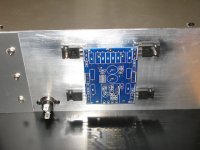
I tested my air tunnel heatsink with the Aleph J board idling and believe it to be up to the job of cooling the MOSFETs. I don't have measurements but the '5 second test' was no problem. A couple photos are attached to solicit your comments. The reason I don't have measurements is the subject of a separate post, to follow.
Frank
Frank
Attachments
Smokin'
As a class A tenderfoot and non-ee, I need to ask advice from you generous people.
I made a dumb mistake and installed the wrong value resistors into R2 and R4 of the Aleph J. During heatsink testing, R4 (1/4 w) eventually failed and started smoking. (I should pay closer attention to the "Ks" on those parts!) At the same time, the J74s were running hot. Can I check if they survived without removing them? ...and looking at the attached photo, do *genuine* J74s have the shoulder bend in the outer pins? If I'm also replacing the JFETs, I definitely want the right parts...
Any and all thoughts/suggestions much appreciated!!!
Frank
As a class A tenderfoot and non-ee, I need to ask advice from you generous people.
I made a dumb mistake and installed the wrong value resistors into R2 and R4 of the Aleph J. During heatsink testing, R4 (1/4 w) eventually failed and started smoking. (I should pay closer attention to the "Ks" on those parts!
) At the same time, the J74s were running hot. Can I check if they survived without removing them? ...and looking at the attached photo, do *genuine* J74s have the shoulder bend in the outer pins? If I'm also replacing the JFETs, I definitely want the right parts...Any and all thoughts/suggestions much appreciated!!!
Frank
Attachments
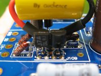
Genuine Toshiba jfets can come in many shapes and looks, depending on year and plant they were made. There's really no meaningful way to test them in circuit except see if they work.
Best, Bill
Thanks Bill. There is plenty of case work to do while some new parts ship...
Hi,
I am finaly populating my circuit boads, this may sound like a stuped question, but how do I determine which leed is positive or negative, there is a white line the length of the 220uF Q2 & Q3, but it dose not have a '+' or a '-' on it like my other electrolytic capacitors do ?
Thank You for your help
I am purchasing more JFETs for my project because I did not initally notice that I should use 2SJ74-BL for the Front End power as well, the question being I have noticed a 2SJ74-V and dose it perform better than the 2SJ74-BL.
Dose the 2SJ74-BL replace Q2, and dose there exist JFETs for replaceing Q3 & Q4 ?
Thank You For Your Help
Ian Scaiff
(scatterbrain001)
Dose the 2SJ74-BL replace Q2, and dose there exist JFETs for replaceing Q3 & Q4 ?
Thank You For Your Help
Ian Scaiff
(scatterbrain001)
two times transformer increase in amps
Hi everyone,
I could only find a 600VAC transformer with dual 18volt secondary when purchaseing them, could I put two 600VAC with dual 18volt 18Amp secondary transformers together to get an equal to one 1200VAC with dual 18volt 36Amp secondary transformer ?
Thank You For Your Help
Ian
Hi everyone,
I could only find a 600VAC transformer with dual 18volt secondary when purchaseing them, could I put two 600VAC with dual 18volt 18Amp secondary transformers together to get an equal to one 1200VAC with dual 18volt 36Amp secondary transformer ?
Thank You For Your Help
Ian
I have populated the circuit boards but not souldered them yet, am I only populating one of the two CCS marked out on the front end circuit board ?
Do you know anything about the 2SJ74-V JFET before I purchase a few 2SJ74-BL JFETs ?
Thank You
Ian
high IDSS 2SJ74-BL JFET
I dont know what this means "high IDSS", is this good or bad for purchasing decision making, the 2SJ74-BL I am concedering is listed here:
20 X 2SJ74BL (10 Matched pairs) - HIGH IDSS - eBay (item 180690570801 end time Jul-05-11 23:57:06 PDT)
Can anyone help me out with this "high IDSS" JFET dellemma ?
Thank You
Ian
Hi Ian,
the characters after the "2SJ74" say something about the Idss, you can find the exact numbers in Toshiba's data specification:
IDSS classification GR: −2.6~−6.5 mA, BL: −6.0~−12 mA, V: −10~−20 mA.
So now we have some numbers. And if you go to AR2's post with the number 524, you can see how this influences the current going through your transistor.
I don't exactly know, what Idss is still ok. But if you have luck your 2SJ74-V have a low Idss between -10mV and -12mV, and this is exactly what we are aiming for. I think you would be looking for 2SJ74-BL with Idss of ybout -8mV- -10mV.
It would be nice if someone of the experts would have a look on the stuff I wrote.
But, keep the Q3 and Q4 as they are, take the ZTX450 devices, you get them nearly everywhere.
Greetings,
Matthias
I dont know what this means "high IDSS", is this good or bad for purchasing decision making, the 2SJ74-BL I am concedering is listed here:
20 X 2SJ74BL (10 Matched pairs) - HIGH IDSS - eBay (item 180690570801 end time Jul-05-11 23:57:06 PDT)
Can anyone help me out with this "high IDSS" JFET dellemma ?
Thank You
Ian
Don't buy those, they are counterfeit! There is no such thing as high Idss 2SJ74BLs, they stop at 12.5ma. I purchased a quantity of those and returned them after I tested them, very low Gm and very high Vp.
The total front end current is around 8.5ma so each jfet in your pair should be able to pass that amount. You want the Idss to be around 10ma for each one.
Best, Bill
- Home
- Amplifiers
- Pass Labs
- Aleph J-X Amp Project