Please tell me , to Aleph JX what values are P1 and RP?
In alternate current source when using the J74 - C4, Z1, R8, R5 are used?
Which is scheme to connect the J74's?
Thanks!
I just re read the whole thread for the third time and realized that Rp value is not mentioned anywhere, nor is written on the schematic from Peter. Here is someone else that has the same question that I have, but never received the answer, at least not here on the thread. Somehow this seems to be the mysterious value, so if we post it here it will be the first time. If I am missing that post please correct me.
Thanx
AR2
Hello Peter,
I am finishing assembly on my Aleph JX and I am kind of blanked out. For the CCS I am using j74. What is the value for Rp? P1 trimmer value is between 25 and 100 ohms, I believe based on EUVL's post - please confirm.
Next, I am not sure is what is going on with R5 - is this resistor used or not if I am using j74.
Since i am using j74 I know that I do not need to populate CCS on the right size of daughter board, and than in that case C4, Z1 are not used?
Please confirm,
Thank you very much
AR2
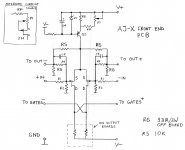
To refresh everybody's memory, I'm attaching proposed FE schematic for the X version.
The value of Rp/P1 was never discussed in depth, and since J74 as CCS was EUVL's idea, you need to contact him directly for any suggestions. In fact Rp is a buffer resistance for P1 and it's value will depend how much adjustment range you require there. You might not need Rp at all; I needed something to 'go over' a trace and thought that instead of a jumper additional resistor could be handy
")
I guess experimenting would be most recommended action here.
In case you are using J74 for CCS, Q2 is not needed and so all the other parts 'around' it, including R5.
Attachments
Last edited:
How do you, who are better resistors to Aleph JX : Holco or PRP?
I would suggest using Dale CMF50. They fit board nicely and sound pretty decent. I used them for F5 and didn't notice much difference when switching to Caddock/Vishays.
http://dkc3.digikey.com/PDF/C091/P1890.pdf
To refresh everybody's memory, I'm attaching proposed FE schematic for the X version.
The value of Rp/P1 was never discussed in depth, and since J74 as CCS was EUVL's idea, you need to contact him directly for any suggestions. In fact Rp is a buffer resistance for P1 and it's value will depend how much adjustment range you require there. You might not need Rp at all; I needed something to 'go over' a trace and thought that instead of a jumper additional resistor could be handy
I guess experimenting would be most recommended action here.
In case you are using J74 for CCS, Q2 is not needed and so all the other parts 'around' it, including R5.
Peter, thank you very much for the prompt response. I also contacted Euvil,
and here is his response sent to me. This will greatly round up your info and shed the light on the last part of I am expecting great project. Here is quote from Euvil's email:
" The exact value for the source resistor depends on the Idss. If the Idss is 8mA, the resistor value is 0.
I suggest you start with a JFET (J74) with Idss of around 10mA, and use a 100R trimpot to trim.
Once the amplifier is fully set, you should consider replacing the trimpot with fixed resistors. "
Thank you Peter and Patrick!
low voltage effects
I don't think this question has been fully answered yet and was wondering if someone could elaborate. Is there a performance penalty (i.e., loss of dynamics, lower wattage output, etc.) if the rail voltage supplying Peter Daniel's boards is lower than the specified +/- 24V? Is +/- 20V acceptable (the readings across power resistors is around .530 over .47Ohm, so current I believe is OK)? At what point is the voltage too low for the circuit to function properly? And what is too high (assuming you increase the voltage rating of power supply caps to say 35V, can you safely increase the voltage input to 30V, for example)? Thanks in advance for any/all insights.
I don't think this question has been fully answered yet and was wondering if someone could elaborate. Is there a performance penalty (i.e., loss of dynamics, lower wattage output, etc.) if the rail voltage supplying Peter Daniel's boards is lower than the specified +/- 24V? Is +/- 20V acceptable (the readings across power resistors is around .530 over .47Ohm, so current I believe is OK)? At what point is the voltage too low for the circuit to function properly? And what is too high (assuming you increase the voltage rating of power supply caps to say 35V, can you safely increase the voltage input to 30V, for example)? Thanks in advance for any/all insights.
I don't think this question has been fully answered yet and was wondering if someone could elaborate. Is there a performance penalty (i.e., loss of dynamics, lower wattage output, etc.) if the rail voltage supplying Peter Daniel's boards is lower than the specified +/- 24V? Is +/- 20V acceptable (the readings across power resistors is around .530 over .47Ohm, so current I believe is OK)? At what point is the voltage too low for the circuit to function properly? And what is too high (assuming you increase the voltage rating of power supply caps to say 35V, can you safely increase the voltage input to 30V, for example)? Thanks in advance for any/all insights.
My guess is that jfets are not going to like higher voltage. The lower voltage could be compensated with higher bias that flows through the output fets. I would say you do not want to go bellow 20V on the rails. My estimate is that you would not want to go above 26 - 28 V.
You might actually be able to get away with a much lower trimpot value than 100 ohm (e.g. 50R or even 20R), but since I always recommend replacing trimpot with fixed resistors, it does little harm to start with 100R. The total dissipation on a 100R trimpot will be 6.4mW (assuming 8mA), which is nothing.
If however you are going to use +/-24V rails (or higher), the J74 will see (24Vx8mA) = ca. 200mW, which is quite a lot. So either you use a heatsink on the TO92 (recommended anyway), or (not exclusive OR) you use a resistor to drop the voltage seen by the JFET to 10V or so (meaning Rp =1.8k 0.5W, preferably 1W). Wire wound resistors will be just fine, since you want constant current anyway. So some inductance will actually help. You can also put a cap after Rp before trimpot to Ground for extra PSU filtering. I use 2200uF myself (only because I have lots of them).
If there is sufficient interest, I shall make a custom TO92 heatsink available, similar to my Dual JFET heatsink.
http://www.diyaudio.com/forums/group-buys/135359-toshiba-dual-jfet-heatsink.html
Patrick
Last edited:
As I am writing this report I am listening to Aleph JX. I am done with one channel, so that i could check if everything is OK.
Very nice sound and plenty of power. It nicely heats up the room, so that I do not need to use anything else for heating.
On Rp I used 1.2 Kohm instead of just short. Rg has to be more powerfull than 3W, for sure. I used what I had handy and that is 27 ohm 25 W, and that works well, no heat there. I had 33 ohm 3 W, there and they were getting pretty hot when turned on. The reason is most likely when for first time plugged, all the current was flowing through those two guys. I do not know how much that changes after the adjustment, didn't change it yet. I am little bit reluctant, based on how hot it was. So, my suggestion is - go with something much bigger for Rg and if you want change later once you have everything set up.
I was very careful in matching jFets, so my offset between the two is very well balanced. It would be really nice feature to add trimmer between the two jFet sources in order to align them if they are not well matched. It takes a while to fix the DC offset while the case is taking on heat and the temperature rises. With that I am talking about voltage between the outputs and ground. Voltage between the two outputs is very close to 0 so no worries there.
Thank you Nelson, Peter and Euvil!
Power for Rg = Rail voltage square/Rg/2.
So if you use 24V rails and 33R, you need about 10W. If you use 100R you need 3W.
I use myself 100R Caddock MP930. I usually use a factor of 10 margin on rated power of resistors.
There is no reason to have trimmer at the JFET diff pair source, because it will only further reduce open loop gain and would not improve distortion cancellation. If only for differential DC offset adjust, it is easier to adjust the Aleph current sources. If the JFET match is not perfect, you will end up with a slightly different bias between the left and the right halves at the power MOSFETs, and hence slightly different heat dissipation. So get properly matched JFETs. They also give you better even harmonic cancellation as a bonus.
And BTW, my codename is EUVL, and not EUViL. The code EUVL has a specific meaning which is anything but evil.
You are of course most welcome to call me Patrick instead. I don't think there are many "Patrick"s here.
Patrick
Last edited:
Power for Rg = Rail voltage square/Rg/2.
So if you use 24V rails and 33R, you need about 10W. If you use 100R you need 3W.
I use myself 100R Caddock MP930. I usually use a factor of 10 margin on rated power of resistors.
There is no reason to have trimmer at the JFET diff pair source, because it will only further reduce open loop gain and would not improve distortion cancellation. If only for differential DC offset adjust, it is easier to adjust the Aleph current sources. If the JFET match is not perfect, you will end up with a slightly different bias between the left and the right halves at the power MOSFETs, and hence slightly different heat dissipation. So get properly matched JFETs. They also give you better even harmonic cancellation as a bonus.
And BTW, my codename is EUVL, and not EUViL. The code EUVL has a specific meaning which is anything but evil.
You are of course most welcome to call me Patrick instead. I don't think there are many "Patrick"s here.
Patrick
Hello Patrick,
Sorry for the wrong spelling.
Yes I have 24V rails and it was obvious that they are taking too much heat. In the Peter's schematic that came with boards 33 ohm and 3W was specified and that is what I ordered parts wise. So if anyone else is building the JX here is the perfect description from Patrick and my experience.
Regarding the jFets, my jFets were really well matched, so I had no problem with difference.
Thanks for the response
AR2
Patrick,
I am happy for you that the amp turned out so nicely. This particular X version was not as yet proven so you are the beta tester.
In your statement concerning plenty of power what ohm speakers are you using and how efficient do you think they are. The power output of these amps has always been a concern of mine. I do not have Feastrix or Jordan high efficient speakers.
What heatsinks are you using?
Way to go. Any Pics??
Tad
Ha, ha now we have a real name mix up. No problems.
I am assuming, your question is related to me, no to Patrick based on your quotes from my post, but as far as I know Patrick is the only one and first really that constructed JX version, as far as I know.
I was just moments ago starting to do measurement, but I had to stop, my family needed me. In a day or two I will post exact measurements.
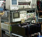
To answer your question, regarding my set up: The case is the one that Mr. Pass generously donated during the Burning Amp. I am using it as a test bed to try different set ups and amps. What I have planned is F5, F5 balanced, F5 cascoded, F3, Aleph JX, Babelfish, Burning Amp 1 and Burning Amp 2 and who knows what else comes up.
Here is the picture of the set up:
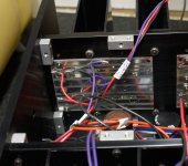
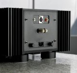
I am using transformers that are also coming from Mr. Pass and 2007 Burning Amp. Those are center taped 45 -35-0-35-45 with 120 and 220 primaries and they are I believe 3-4 KVA each. I am using two in order to get dual secondaries wired for 220V which gives me on 35V outputs exactly 24V unloaded after rectification.
Here are the transformers:
I am assuming, your question is related to me, no to Patrick based on your quotes from my post, but as far as I know Patrick is the only one and first really that constructed JX version, as far as I know.
I was just moments ago starting to do measurement, but I had to stop, my family needed me. In a day or two I will post exact measurements.
To answer your question, regarding my set up: The case is the one that Mr. Pass generously donated during the Burning Amp. I am using it as a test bed to try different set ups and amps. What I have planned is F5, F5 balanced, F5 cascoded, F3, Aleph JX, Babelfish, Burning Amp 1 and Burning Amp 2 and who knows what else comes up.
Here is the picture of the set up:
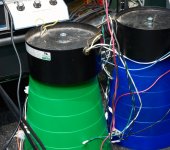
I am using transformers that are also coming from Mr. Pass and 2007 Burning Amp. Those are center taped 45 -35-0-35-45 with 120 and 220 primaries and they are I believe 3-4 KVA each. I am using two in order to get dual secondaries wired for 220V which gives me on 35V outputs exactly 24V unloaded after rectification.
Here are the transformers:
Attachments
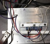
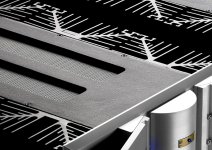
OK here is Peter's rectifier board temporary mounted on the heat sink.
Now, everything is temporary and very ugly at this point. I am using wires to connect everything in order to accommodate all the set ups I would like to do.
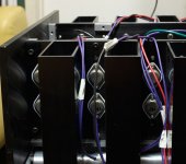
So far I did F5 and F5 balanced, and liked it very much. Here is the shot of that. Here you could see the boards that are connecting TO3 IRF devices. There are 6 P and 6 N devices per side, what makes it ideal to do different configurations. And here are the devices seen from outside.
Now, everything is temporary and very ugly at this point. I am using wires to connect everything in order to accommodate all the set ups I would like to do.
So far I did F5 and F5 balanced, and liked it very much. Here is the shot of that. Here you could see the boards that are connecting TO3 IRF devices. There are 6 P and 6 N devices per side, what makes it ideal to do different configurations. And here are the devices seen from outside.
Attachments
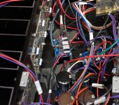
Like I explained, it is very ugly at this point, but very functional to what I am trying to do. Here is the shot of JX while I still have F5 in the case, so I am using the rest of the N devices in order to see how JX works. The case survived really well heating, no problems there.
I did test with total 4 devices per side, and like I explained I have only one channel so far. My test speakers are around 93 dB and they are 6 ohms. My lab, I was listening in, is not too big, but I do have experience with that space and speakers so I know how it will sound in my main system and room.
My interest is mostly to find the amp that has more power than Aleph 30, I am using now, but with that marvelous top end that amp has. I am using Aleph 30 to drive my ribbons in my active three way system. The the new amp I am searching for, will be driving my new set up for ribbons and mids. I would like to have that top end with plenty of headroom.
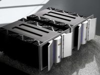
Bass I am driving with X600 that I made. Here are the pictures of that as well.
I hope I answered your questions. In a few days i will follow up with the measurements.
I did test with total 4 devices per side, and like I explained I have only one channel so far. My test speakers are around 93 dB and they are 6 ohms. My lab, I was listening in, is not too big, but I do have experience with that space and speakers so I know how it will sound in my main system and room.
My interest is mostly to find the amp that has more power than Aleph 30, I am using now, but with that marvelous top end that amp has. I am using Aleph 30 to drive my ribbons in my active three way system. The the new amp I am searching for, will be driving my new set up for ribbons and mids. I would like to have that top end with plenty of headroom.
Bass I am driving with X600 that I made. Here are the pictures of that as well.
I hope I answered your questions. In a few days i will follow up with the measurements.
Attachments

Ar2 and Patrick have both balanced F5 and JX right? Impressions guys, what are the differences?
It is too early to make any worthy judgement for me since I completed only one channel of JX. F5 is such a good amp. Great balanced sound. There is bass and there is awesome top end. My opinion is that every DIYer ought to make one F5 for himself. It is simple and easy to make and it sounds magnificent.
It is not too demanding on heat sinks - relatively speaking - and the bass coming out of that small amp is pure miracle. It lacks the power for not as sensitive speakers, but it is all that amp suppose to be sound wise.

(instead of 3 kisses)
Not to get anyone weird ideas.
 Three kisses are serbian custom.
Mr. Zen Mod is my skype teacher!
- Home
- Amplifiers
- Pass Labs
- Aleph J-X Amp Project