Better connection to just solder wires to bare metal - can get plain terminals - perhaps, send the crimping tool back for refund if unable to make it work.
Suggest using 1/4" QC connectors (6.25mm blade & clip type) that are 'the standard' push-on type used everywhere in industry.
I use the transistor clips to hold down the Fets so avoid the screw/thread thru the power fet body - commonly available - try Jaycar, etc here in Oz - simple, effective, flexible.
and have bought an expensive ratchet crimping plier
but am unable to apply enough force to crimp the connectors.
If you peel away the plastic from the connector, you will be able to solder them. You most likely can use the ones you have, instead of ordering something new.
Thanks James and 6L6. I have found someone who has done most of the crimping for me. Incredible how much force is needed, even with an expensive pair of pilers.
I also found some solder eye/ring connectors:
Montagemateriaal - Soldeerlippen - EOO - ElectronicaOnderdelenOnline
Have not bought them yet, but hope to use these in the future.
One question remains:
I need to tap holes into the heatsinks and will probably out-source to a local metal shop. What size thread (M3, M4, etc) do I need for the MOSFET's? And what depth? Metric answers, please")
Anyone?
Thanks,
Albert
I also found some solder eye/ring connectors:
Montagemateriaal - Soldeerlippen - EOO - ElectronicaOnderdelenOnline
Have not bought them yet, but hope to use these in the future.
One question remains:
I need to tap holes into the heatsinks and will probably out-source to a local metal shop. What size thread (M3, M4, etc) do I need for the MOSFET's? And what depth? Metric answers, please
Anyone?
Thanks,
Albert
To mount the fets, I would suggest M3 with a large washer (On this side of the pond we call them 'fender washers', I have no idea if it's the same or different in the Queen's english...)
As for the holes in the heatsinks, drill through and tap the entire length. Then you don't have to worry about finding an odd length screw.
As for the holes in the heatsinks, drill through and tap the entire length. Then you don't have to worry about finding an odd length screw.
Ah Albert,
A novice Aluminium tapper, eh?
Well, a couple of things -as Jeremy mentioned, a 3mm screw goes thru the big power Fet and the depth of thread is .....
The power fet is 5mm thick (fom memory)and if you add a big flat washer plus Kerotherm underneath, this will add up to about 7mm total thickness, okay - and if you use the socket head set screw (Allen key head and fully threaded) they usually come in multiples of 5 mm length these days (ie 10mm, 15mm, etc) and as you would want more than 3mm thread of a 10mm screw into the heatsink, your're looking at a 15mm screw (M3 x 15mm) the heatsink tapped depth to be at least 8mm
Now, if you're doing this yourself, you need to start the threading with a particular tap called a "Tapered tap" that allows an easier start in the job, complete with "thread cutting fluid for aluminium, not steel, plus using a gadjet called a "tapping guide" (a peice of metal with a 3mm hole in it that keeps the tap vertical as you twist it into the heatsink - as 3mm taps are pretty brittle, need to get a couple spares.
When you have the initial tapered holes done, you then run the "Bottom tap" thru the same hole to make sure the thread is completely formed to the full depth of your initial drill hole, for your job this would be at least 8mm, okay?
When this is done, you need to wash all the "swarf" and rubbish out of the hole before test fitting the screw to check the job. This has to be properly done to make sure that you don't overtighten the screw on the Fet when finally 'fit-up'
As you can see, the idea of using the more robust 4mm taps/screws and a flat bar across the back of the power fet is far easier, even tho you need twice as many holes.
One of the reasons I use the "transistor clips" is that it only needs the 1 hole/power Fet and allows for many times to dissassemble the Fet without any difficulty - a thing I tend to do fairly often when optomising/changing circuit components - they're available from both ]RS' and 'Element 14' over there, I think, and Jaycar here and in the UK.
I hope this has been useful ....
Thanks everyone for you comments and suggestions.
I am going to outsource the threading of the sinks for this amp, but will try it myself in a future build. I have copied your comments for future reference!
A problem with outsourcing is that you only get one shot to get is right. For this reason I think I am going to use the alubar option. The holes do not have to be "exactly in the right spot". As long as the MOSFETs can be connected to the PCB and enough (I know, not too much) pressure is applied, it should be OK.
The crimping has been going so, so. I have been able to crimp a few myself, but have often had to leave the connector (stuck) in the pliers till someone else was around to finish the crimp. Not ideal, but most are now done. For some, I have peeled away the insulation and have been able to solder the connections.
I am hardwiring the PSU. I am using Apexjr 33000uF caps
http://apexjr.com/images/Nippon50v33000uf.jpg
and these did not fit the Peter Daniels PSU board.
My CRC PSU consists of:
each rail:
1 x 225VA Amplimo transformer with 2 x 10.5V secondaries but connected serially to give 21V AC (cheap from surplus shop)
GPBC bridge rectifier
C: 1 x 33000uF 50V cap + 2K2 3W bleeder resistor
R: 4 x 0R47 3W resistor or wire
C: 1 x 33000uF 50V cap + 4u7 400V Met-Poly NPTM cap (also Apexjr)
Wiring of PSU (from bridge rectifier onwards) is 14AWG silver plated stranded copper from Apexjr (nearly all the PSU parts come from Apexjr or other surplus shops, haha).
I have thought about using other diodes for the rectifier but am using the GPBC I had already bought. I recently got some MUR3020W in a GB, but will keep them for a future version. Might try these to see if they make a difference. I think they fit the Peter Daniels rectifier boards, so should be worth a try.
I hope to finish the amp relatively soon and am anxiously awaiting its sound. I have an old (original) Aleph 3 and hope to be able to say (like Nelson) that I like the J best
Will post photo's in pictures thread soon.
Albert
Shew ... read through 125 pages ... <so tired>
Anyway, I saw this addressed a few places, but wanted clarity.
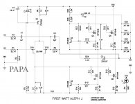
If I only plan to use SE input, can I just omit R3 and C1 or must I ground the input side of R3? I am curious as a quality poly film 1uF isn't a "cheap" component and I'd like to omit if possible since I will never pass signal through it.
Anyway, I saw this addressed a few places, but wanted clarity.
If I only plan to use SE input, can I just omit R3 and C1 or must I ground the input side of R3? I am curious as a quality poly film 1uF isn't a "cheap" component and I'd like to omit if possible since I will never pass signal through it.
for SE input : short instead of C1 , ground R3
Thanx!
Problem with new build
Hi guys,
I finally got my powerchord for my variac and was able to test my new Aleph J this evening.
Quick recap of the setup:
I switched off the unit. Voltage dropped very, very slowly. When it was 0V I took out the variac and connected straight to mains. I switched the unit back on and had +30.5V and -30.5V DC (no load).
I then connected the amp boards and had nearly NO voltage. Checked to see what was going on and found that both fuses had blown.
I knew that the 1.6A could be a bit too small (1.6A is correct size for 300VA dual 18V secondaries) so increased fuses to 2A slowblow each.
I then disconnected power to both amp boards and switched the unit back on. No problem, +30.5V and -30.5V DC (no load).
I switched the unit off and waited for the voltage to drop. I then connected the right channel only. Switched the back on. Voltage steady at +27.3V and -27.3V DC.
The problem is that I have -24V on the speaker output!
I disconnected the right channel and connected the left channel only. Exactly the same problem.
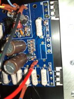
Interestingly I noticed that the heatsink with Q5 and Q6 gets warm/hot, while the heatsink with Q7 and Q8 remains cool.
I am using Peter Daniel boards. JFets and Mosfets came from a reputable source (Hannes aka h_a). All other parts from Mouser and Digikey. Case is Modushop 4U 400mm full aluminium. Mosfets attached to heatsink using Kerafol.
Any suggestions? What should I try/do?
Thanks,
Albert
Hi guys,
I finally got my powerchord for my variac and was able to test my new Aleph J this evening.
Quick recap of the setup:
- mains protected by 2 x 1.6A slowblow fuse
- 1 leg of mains supply through CL-60 as inrush suppressor
- 2 x 225VA Amplimo transformer, each with dual 10.5V secondaries. I am using one transformer (21V AC) for each half of the PSU.
- 2 rails with CRC setup:
- 33000uF/50V Nippon Chemi + 2k2/3W bleeder
- 4 x 0R47/3W
- 30000uF/50V Nippon Chemi + 4k7/400V NPTM
I switched off the unit. Voltage dropped very, very slowly. When it was 0V I took out the variac and connected straight to mains. I switched the unit back on and had +30.5V and -30.5V DC (no load).
I then connected the amp boards and had nearly NO voltage. Checked to see what was going on and found that both fuses had blown.
I knew that the 1.6A could be a bit too small (1.6A is correct size for 300VA dual 18V secondaries) so increased fuses to 2A slowblow each.
I then disconnected power to both amp boards and switched the unit back on. No problem, +30.5V and -30.5V DC (no load).
I switched the unit off and waited for the voltage to drop. I then connected the right channel only. Switched the back on. Voltage steady at +27.3V and -27.3V DC.
The problem is that I have -24V on the speaker output!
I disconnected the right channel and connected the left channel only. Exactly the same problem.
Interestingly I noticed that the heatsink with Q5 and Q6 gets warm/hot, while the heatsink with Q7 and Q8 remains cool.
I am using Peter Daniel boards. JFets and Mosfets came from a reputable source (Hannes aka h_a). All other parts from Mouser and Digikey. Case is Modushop 4U 400mm full aluminium. Mosfets attached to heatsink using Kerafol.
Any suggestions? What should I try/do?
Thanks,
Albert
Attachments
Hi Zen Mod,inputs shorted to gnd ?
I just rechecked. Both + and - are shorted.
- Home
- Amplifiers
- Pass Labs
- Aleph J Schematic