Blues said:Thanks so much, John. Something to play with on a long flight.
Be sure to show us what you come up with.
")
> I'm playing with an Aleph J with LU1014D cascodes on the lower half. I've got the three volt spread that the LU1014D wants, but I'm stuck with six amps regardless of what value I use in its source resistor. It wants about half that amount......
It sounds like the LU1014 is overbiased.
The LU1014 Cascode wants to see 0V Vgs at the gate of the power JFET (i.e. the gate is at the same voltage as the negative rail for the lower devices), whereas the standard Aleph J circuit will give you about 4V.
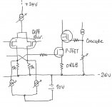
The simplest solution is to use a current source (2SK170BL with the same Idss as your diff pair bias) to drain off the diff pair current to a more negative rail (at say 10V lower than the negative rail). That means one extra power supply (for 20mA or so) and 2 JFETs.
It has been discussed elsewhere. Nelson had the same proposal.
http://www.diyaudio.com/forums/showthread.php?postid=1361918#post1361918
Or you have already implemented this ? Then please post your schematics.
Patrick
It sounds like the LU1014 is overbiased.
The LU1014 Cascode wants to see 0V Vgs at the gate of the power JFET (i.e. the gate is at the same voltage as the negative rail for the lower devices), whereas the standard Aleph J circuit will give you about 4V.
The simplest solution is to use a current source (2SK170BL with the same Idss as your diff pair bias) to drain off the diff pair current to a more negative rail (at say 10V lower than the negative rail). That means one extra power supply (for 20mA or so) and 2 JFETs.
It has been discussed elsewhere. Nelson had the same proposal.
http://www.diyaudio.com/forums/showthread.php?postid=1361918#post1361918
Or you have already implemented this ? Then please post your schematics.
Patrick
Blues said:Try setting the bias current at the CCS on top. Check Zv9 too for the bottom part.
Thanks Allan and Patrick!
Just before bedtime last-night I discover that the upper current had to be lowered to assist controlling the LU1014D current value. So , thanks for adding the tip Allan--and showing interest.
I have time later today to play. I'm not quite there, but will post what I've accomplished so far.
Patrick, I've always valued your posts and will follow the link you offered. You suggestion is insightful. I'll take time to digest the contents.
Best regards.....
Hi Carpenter,
I played with such a thing here,
http://www.diyaudio.com/forums/showthread.php?s=&threadid=122175
I only had a short glance at your schematic, but it seems you're running at stock 1.3A and in this case the source resistors of the LU1014 are too high and won't give loadline cancelation.
For loadline cancelation you need about 600mV per amp if I remember correctly (you can check that value in the Zen#9 article).
Then it needs to run self-biased! Check the graph Patrick posted once.
Next I don't see how you got rid of the DC at the gates (no cap, no additional rails), with the stock 3.5V UGS you're just grilling the jfet.
Last, you will get funny frequency response peaks that you can tame as Patrick suggested with either a Zobel or by finding an elegant solution for the cascode-divider impedance (which I didn't so far).
If you simulate damping factor you will find that it performs on the same level as the original J (about 20), which I would like to get a bit higher. Only way would be by increasing NFB, but then you open just another can of worms
Have fun, Hannes
Hannes, Patrick, and Ian--you guys are terrific!
After work, today, I'll read more posts (the link is much appreciated, Hannes) and study the ideas presented (thanks for the excellent artwork, Patrick).
Ian, you're a peach. Thanks for offering to pitch in with supplies.
John This is certainly an enjoyable experience.
After work, today, I'll read more posts (the link is much appreciated, Hannes) and study the ideas presented (thanks for the excellent artwork, Patrick).
Ian, you're a peach. Thanks for offering to pitch in with supplies.
John
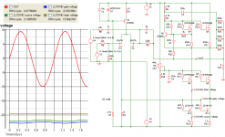
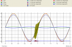
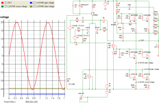
This is certainly an enjoyable experience.Here's a pic of the cascode version transposed over the original Aleph J. Both are initially fed +/- 1 volt at the inputs. The cascode version has some horrible anomaly/distortion when it bottoms out against the LU1014Ds drain voltage--the Aleph J doesn't suffer from this fate.
I backed the inputs of the cascoded version off to 900mV on the +/- inputs. The anomaly/distortion disappears (purple line sine wave).
So, I'm reading Patrick's link and can't quite get my mind around the entire problem. If I can't run the cascode quite as hard as the Aleph J, that's OK with me... or is there something more sinister going on here.
Attachments
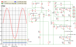
Your potential divider (R2/R16) from the previous post just reduced the open loop gain by a factor of 10, so you end up with very little negative feedback (<< 10 on 8 ohm).
Why not trust me and Nelson for once and change the circuit as I proposed in the sketch. All you need is a 9V battery, 2 JFETS (2SK170GR or BL) with an Idss of 4mA matched, or use 2x J511 current regulating diode, as the 2 lower current source. Then set the current source of the diff pair so that the voltage across the 1k drain resistors (R2 in your original circuit) of the diff pair is 0V. Now you should get about 1.3A bias of the LU1014s and full performance from the circuit.
PS You need to replace R1 by a 2k trimpot to enable you to adjust the diff pair current. Also R22, R23 should be about 0R68 for best linearity of the LU1014s. If you are only build AJ and not AJX (balanced version), then you only need to change 1 side of the diff pair, i.e. with one 9V battery and 1x J511. Can't be much easier and will cost you less than $3-.
Patrick
It's not a matter of trust, Patrick. I post what I understand and hope that enlightened members with continue to share their insight with me.
I played with yours and Nelson's circuit and failed. I'm still tinkering, but in the meantime, I thought I'd post something that I found interesting.
Thanks for explaining how a potential-divider can alter negative-feedback.
I played with yours and Nelson's circuit and failed. I'm still tinkering, but in the meantime, I thought I'd post something that I found interesting.
Thanks for explaining how a potential-divider can alter negative-feedback.
EUVL said:Then set the current source of the diff pair so that the voltage across the 1k drain resistors (R2 in your original circuit) of the diff pair is 0V. Now you should get about 1.3A bias of the LU1014s and full performance from the circuit.
Very useful information! I couldn't get a sine wave before you offered this bit of info. By lowering the value of R1 I'm in business. Thank-you.
- Home
- Amplifiers
- Pass Labs
- Aleph J Schematic