What did you put in R7? Both the 2K pot and the 1K fixed?
What do you have for R8? 1K fixed or a pot set at 1K?
Gentleman I am sorry for my mistake. I should have said the R27 pot. The one that controls the bias. There is a place there for a R27 resistor with nothing stated on the BOM other than the pot.
Last edited:
Are you talking about R7 or R27?
You are correct R27, bias pot. Right next to C2 is a place for a resistor called R27 as well.
R27. SEE TEXT
Let's talk about this - as it is somewhat confusing.
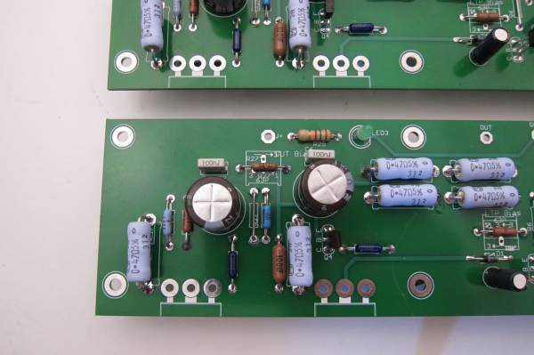
There are 3 places for R27 on this PCB. The first is the pad next to the cap C2. (in the above photo it is empty) I suggest making that one a jumper.
Where the jumper is placed in the photo should be open, and under the green insulation you will find the place for a pot.
SO - place a 100K pot where the pot will fit and jumper the vertical 'R27'. Set the pot to 68K before you turn the amp on the first time.
Note that in this photo, the vertical R27 is jumpered, and there is a 68K resistor in the horizontal spot. I later replaced the resistor with a pot.
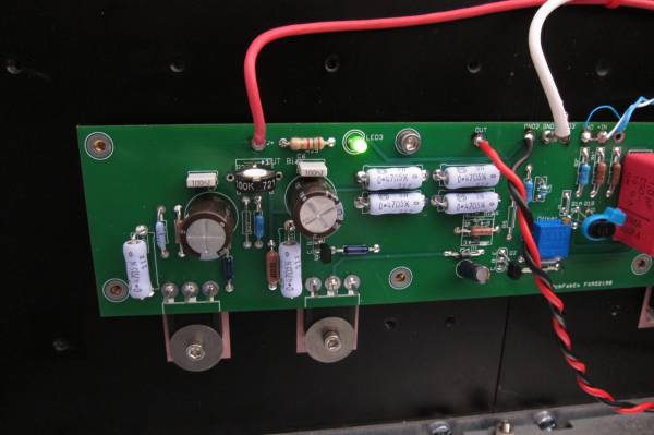
Here is the pot in that position. I used a single-turn because I had one on hand... I strongly suggest multi-turn pots on all of these projects.
 The photos are off-site and small, the various jumpers and such are not covered very well,(or at least well enough to be clear...) generally it's needing an update because it's still a very popular project.
Are you talking about R7 or R27?
I see now that you say in your build guide to put a jumper in the R27 resistor spot next to C2.
Do I still need to put a jumper across the R27 pot as well? On these boards there are holes on both sides of the R27 pot. I see in the above picture you have a resistor across the R27 pot.
I am thinking now R27 jumper and R27 pot place my pot. I think you have that resistor there to replace the pot in some cases. Am I correct?
Last edited:
OK, can adjust DC offset and bias now with jumper at R27 along with pot.
I have a 500R pot at place R8 following the BOM and I notice in the build guide 6L6 has a resistor in that spot instead of a pot. What resistor should I put there or how do I adjust R8 pot? It says LTP bias whatever that is.
I have a 500R pot at place R8 following the BOM and I notice in the build guide 6L6 has a resistor in that spot instead of a pot. What resistor should I put there or how do I adjust R8 pot? It says LTP bias whatever that is.
Up and running great. I had not hooked up the wiring on one channel so I removed the R8 pot and installed a 1K resistor as suggested above. On the other channel I went ahead a fired it up with the one turn pot centered. Did the NP FW Aleph J have a pot for R8 and if so how is it adjusted. I am going to assume it did have the 500 ohm pot per the BOM but I cannot find any info on how it is adjusted. It appears to my eyes that it controls the V's to the Q2 cascode BJT emitter. I am going to guess that one would use the R6 resistor to measure from. Maybe someone with more talent can tell me more about the circuit.
Tomorrow I do plan on replacing the R8 pot with the 1K resistor but my curiosity is aroused. By the way the amp has the familiar SE mosfet sound like I have heard and love from the FW designs. This is after a very short 1 hour listening session.
Tomorrow I do plan on replacing the R8 pot with the 1K resistor but my curiosity is aroused. By the way the amp has the familiar SE mosfet sound like I have heard and love from the FW designs. This is after a very short 1 hour listening session.
The factory Alephs did not have any potentiometers. They are added (along with a few of the jumpers) back when the Toshiba were getting scares and the supply of replacement J74s did not yet exist, so the PCB was made to accommodate other devices if needed.
It wasn't, but the extra bits are all there.
There is no need to twiddle the pot, as the input stage CCS voltage is almost entirely controlled by the zener.
It wasn't, but the extra bits are all there.
There is no need to twiddle the pot, as the input stage CCS voltage is almost entirely controlled by the zener.
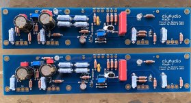
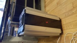
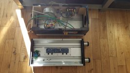
I built mine from a couple of reclaimed LED light fittings.
Thanks to all the folks on here I managed to diagnose a slight problem during set up but it is now the pride of my Hi-Fi system.
Mine uses a single transformer but dual bridge / capacitor configuration.
I find this more than adequate with a 600VA transformer and 4 x 33000uF caps.
Thanks to all the folks on here I managed to diagnose a slight problem during set up but it is now the pride of my Hi-Fi system.
Mine uses a single transformer but dual bridge / capacitor configuration.
I find this more than adequate with a 600VA transformer and 4 x 33000uF caps.
Attachments
Last edited:
I built mine from a couple of reclaimed LED light fittings.
Thanks to all the folks on here I managed to diagnose a slight problem during set up but it is now the pride of my Hi-Fi system.
Mine uses a single transformer but dual bridge / capacitor configuration.
I find this more than adequate with a 600VA transformer and 4 x 33000uF caps.
If anybody was curious, the conclusion to his setup saga is here. It illustrates a good learning point for all. We should check to make sure that all the leads of all semis and passives have good continuity into the PCB!
https://www.diyaudio.com/forums/pass-labs/353472-aleph-setting-dc-offset-15.html#post6236826
Best,
Anand.
I built mine from a couple of reclaimed LED light fittings.
Thanks to all the folks on here I managed to diagnose a slight problem during set up but it is now the pride of my Hi-Fi system.
Mine uses a single transformer but dual bridge / capacitor configuration.
I find this more than adequate with a 600VA transformer and 4 x 33000uF caps.
Repurposing in any context is desirable for more reasons than just having a unique amp case.
That in itself is reason enough, however.
Looking good, Dad.
- Home
- Amplifiers
- Pass Labs
- Aleph J illustrated build guide