Had to file down the cutout a millimetre or so... I started with Dremel DC drill and grinding stone, but switched to a hand-driven file which did the job fine because the back panel is soft aluminium-like alloy.
The reasons I chose the IEC filter mains block are few:
- I did not want to use the little telephone lugs and jumper links on a block that comes from the diyAudio store
- didn't want two fuses
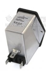
- the Schaffner block has the suppressor chokes and X/Y capacitors; I have obtained very good results with these filters before in all my builds/mods.
- it also has a metal shield that automatically guarantees the chassis/case is grounded (with a little help from my end in scraping off the paint where the mounting screws go)- see the attachment.
- didn't want to use the mains terminal block/ didn't want to mess around with an "external" X2 capacitor - was basically after a clean build/look.
The reasons I chose the IEC filter mains block are few:
- I did not want to use the little telephone lugs and jumper links on a block that comes from the diyAudio store
- didn't want two fuses
- the Schaffner block has the suppressor chokes and X/Y capacitors; I have obtained very good results with these filters before in all my builds/mods.
- it also has a metal shield that automatically guarantees the chassis/case is grounded (with a little help from my end in scraping off the paint where the mounting screws go)- see the attachment.
- didn't want to use the mains terminal block/ didn't want to mess around with an "external" X2 capacitor - was basically after a clean build/look.
Attachments
Last edited:

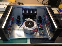
So much room inside that large chassis! Go ahead and crank the bias current up to 1 Amp per device (470 mV across the source resistors), as recommended by 6L6 in the first page of this thread. The amp will continue to sound better and better as everything settles in over the next week or so.
Once it has settled in, try adding some high quality 470 uF or 1000 uF capacitors on the outputs of your power supply. There is an output snubber location that can be used for this, place a jumper across the snubber resistor location. Listen some more...
Once it has settled in, try adding some high quality 470 uF or 1000 uF capacitors on the outputs of your power supply. There is an output snubber location that can be used for this, place a jumper across the snubber resistor location. Listen some more...
Last edited:
So much room inside that large chassis! Go ahead and crank the bias current up to 1 Amp per device (470 mV across the source resistors), as recommended by 6L6 in the first page of this thread. The amp will continue to sound better and better as everything settles in over the next week or so.
Once it has settled in, try adding some high quality 470 uF or 1000 uF capacitors on the outputs of your power supply. There is an output snubber location that can be used for this, place a jumper across the snubber resistor location. Listen some more...
In due time I’ll ramp up the bias
") . I’m at 410mV right now and I can’t get the heatsinks past 44c so definitely some room to go. The room I’m in is about 10 degrees F colder in the winter so I’m going to stay a little conservative!
. I’m at 410mV right now and I can’t get the heatsinks past 44c so definitely some room to go. The room I’m in is about 10 degrees F colder in the winter so I’m going to stay a little conservative!Thanks for the advice on the ps output caps. I didn’t have the patience to read all of the posts in this thread or the power supply one!
Just starting my first Alpeh J build, had some questions
Hi all, I have just started my Aleph J build, this thread is really helping! I did have a few questions
1. I have the DIY Audio 4U chassis and am leaning towards mounting the PSU board vertically on the back of the front panel as there are mounting holes for it there. The toroid transformer would be on the bottom horizontal plate. I have not seen any pictures on this thread of someone doing this type of layout (or perhaps I just missed them). Does anyone see a problem with that approach?
2. I'm a bit surprised that looking at the amp schematic, there does not seem to be any local decoupling on the output transistor supplies rails. I would have expected there to be some caps near the transistors to handle the HF transients, something in the 47uF - 220uF range. Perhaps I have missed it but I also have not seen a discussion about that. I was thinking about adding those and seeing what the effect was on THD with and without. What do you all think about that idea?
Thanks, I will probably have more questions coming ...
Hi all, I have just started my Aleph J build, this thread is really helping! I did have a few questions
1. I have the DIY Audio 4U chassis and am leaning towards mounting the PSU board vertically on the back of the front panel as there are mounting holes for it there. The toroid transformer would be on the bottom horizontal plate. I have not seen any pictures on this thread of someone doing this type of layout (or perhaps I just missed them). Does anyone see a problem with that approach?
2. I'm a bit surprised that looking at the amp schematic, there does not seem to be any local decoupling on the output transistor supplies rails. I would have expected there to be some caps near the transistors to handle the HF transients, something in the 47uF - 220uF range. Perhaps I have missed it but I also have not seen a discussion about that. I was thinking about adding those and seeing what the effect was on THD with and without. What do you all think about that idea?
Thanks, I will probably have more questions coming
...Hi all, I have just started my Aleph J build, this thread is really helping! I did have a few questions
1. I have the DIY Audio 4U chassis and am leaning towards mounting the PSU board vertically on the back of the front panel as there are mounting holes for it there. The toroid transformer would be on the bottom horizontal plate. I have not seen any pictures on this thread of someone doing this type of layout (or perhaps I just missed them). Does anyone see a problem with that approach?
2. I'm a bit surprised that looking at the amp schematic, there does not seem to be any local decoupling on the output transistor supplies rails. I would have expected there to be some caps near the transistors to handle the HF transients, something in the 47uF - 220uF range. Perhaps I have missed it but I also have not seen a discussion about that. I was thinking about adding those and seeing what the effect was on THD with and without. What do you all think about that idea?
Thanks, I will probably have more questions coming
Here’s one
Attachments
Mounding the PSU board(s) on the inside of the front panel is certainly a viable option. There is room for two. The rectifiers will be mounted to the bottom plate. I might suggest a pair of Antek AS-3220 transformers, and 18,000 uF, 50V caps on each of the PSU boards. The Aleph J will make good use of these, and certainly deserves the best dual-mono power supply configuration.
Mounding the PSU board(s) on the inside of the front panel is certainly a viable option. There is room for two. The rectifiers will be mounted to the bottom plate. I might suggest a pair of Antek AS-3220 transformers, and 18,000 uF, 50V caps on each of the PSU boards. The Aleph J will make good use of these, and certainly deserves the best dual-mono power supply configuration.
Amen; TungstenAudio knows whereof he speaks.
If you want to get the most out of your AJ; save yourself some time, trouble and money by going dual mono from the get-go.
I started with single transformer/diyAudio store PS PCB with 18,000uf of 50v caps.
AJ sounded great.
Doubled down on both for dual mono PS.
AJ went from great to superb.
Good evening, gentlemen, I need help finding an error in the commissioning of my Aleph J.
At the first start I had no voltage in the resistor R 16 (0.235 ohm because I use 2 IRFP 150 instead of 4 IRFP 240).
I stopped immediately to check the wiring and circuit.
I forgot the R15 resistor (1K ohm).
I then welded the resistor of 1 K Ohm, turned on the voltage in R16 was 0.580 volt, reduced with the potentiometer of 100 K Ohms in order to have 0.400 volt in R16. Connected to my B1 preamp, no sound in my test HP!!
Forgetting R 15 can damage Q 4 or IRFP 150?
...I have obtained very good results with these filters before in all my builds/mods.
....
Hello Boky,
One question but backround first: I am inclined to use such socket in one of my builds, but i fail to justify the usage. Do you mind sharing but being specific what good results are you reffering? I mean what good would an emi filter do to a linear power supply? We have no outgoing switcjing noise to kill and such noise inbound is basically filtered by the primary itself.
Why oh why i itch of using such a soket myself
? I fear is about looks and not function But damn it looks protected
Last edited:
They provide a broad spectrum attenuation of noise, check the specifications. I used 6A (I think) version; no need for such a high amperage - 4A would be more than sufficient with even better noise attenuation. It all boils down to what you think about the noise in general, experience, and measures taken to combat the rails' noise on the PS and AMP boards.
I also did not want to use the phone lugs on an IEC block that comes from DIY store...
You can experiment and see if you like it or not. You may not like the sound with the filter, especially in combination with fast switching/soft recovery diodes...
I also did not want to use the phone lugs on an IEC block that comes from DIY store...
You can experiment and see if you like it or not. You may not like the sound with the filter, especially in combination with fast switching/soft recovery diodes...
Toroidal transformers have very good bandwidth at high frequencies, and they couple all sorts of mains noise into the secondary. If you use slow diodes without a snubber, there is the possibility of the secondary ringing due to switch noise and making higher harmonic noise on the transformer itself and back into the mains as well.
EMI filters are worthwhile.
EMI filters are worthwhile.
Bonsoir à vous tous.
Comment insérer une image ou un diagramme directement dans le message?
Je vous remercie d’avance.
Toto34.
Pose ta question en anglais ce sera bien mieux
pour les images , il faut d'abord les héberger quelque part , chez casimage ou autre , et ensuite tu met le lien sur ton post
.
- Home
- Amplifiers
- Pass Labs
- Aleph J illustrated build guide