Hi all,
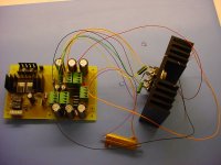
Today, I tested my A2 pcb's on a 1/6th scaled down test rig. For power, I used 2 lab bench power supplies set at 54V 1.5A, and in stead of the high power output stage (the part in the schematic which is multiplied by 6), I used a temporary setup using only 1 pair of fets. (So current drawn by the circuit was just over 0.5A) The load was a single 10 ohm power resistor.
The circuit runs perfectly. I have the mosfets in the differential stage matched up to <10mV, as well as all other semiconductor devices. At first measurements, there seems to be very little channel imbalance between the two PCB's
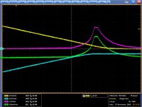
Still there is an issue. There appears to be a large transient when switching on and off the amplifiers. I have attached a scope screenshot from the OFF-thump, which was the worst one compared to the ON-thump.
I am not sure what causes this thump. Of course it could be the setup, since the two lab supplies were not linked, and the two power output devices were not matched at all.
Or perhaps is this behaviour normal for Aleph Amps? Or should I look for an error in the pcb?
Thanks,
Bouke
About the screenshot:
Yellow trace: Positive Supply Rail
Blue trace: Negaive Supply Rail
Pink Trace: Output Voltage
Green trace: Output Current
Today, I tested my A2 pcb's on a 1/6th scaled down test rig. For power, I used 2 lab bench power supplies set at 54V 1.5A, and in stead of the high power output stage (the part in the schematic which is multiplied by 6), I used a temporary setup using only 1 pair of fets. (So current drawn by the circuit was just over 0.5A) The load was a single 10 ohm power resistor.
The circuit runs perfectly. I have the mosfets in the differential stage matched up to <10mV, as well as all other semiconductor devices. At first measurements, there seems to be very little channel imbalance between the two PCB's
Still there is an issue. There appears to be a large transient when switching on and off the amplifiers. I have attached a scope screenshot from the OFF-thump, which was the worst one compared to the ON-thump.
I am not sure what causes this thump. Of course it could be the setup, since the two lab supplies were not linked, and the two power output devices were not matched at all.
Or perhaps is this behaviour normal for Aleph Amps? Or should I look for an error in the pcb?
Thanks,
Bouke
About the screenshot:
Yellow trace: Positive Supply Rail
Blue trace: Negaive Supply Rail
Pink Trace: Output Voltage
Green trace: Output Current
Attachments


Alephs are generally sensitive ( regarding thumps ) only on amount of capacitance in parallel with zener diode , which is in biasing part of input LTP CCS ; if you stay with Papa's prescribed values for that cap , everything is fine
I resume that you have problems with different time constants in your two independent supplies
ppl use these dreky amps even for Lowthers and similar "fragile" spks .... that tells something ....
I resume that you have problems with different time constants in your two independent supplies
ppl use these dreky amps even for Lowthers and similar "fragile" spks .... that tells something ....
Bakmeel said:
About the screenshot:
Yellow trace: Positive Supply Rail
Blue trace: Negaive Supply Rail
Pink Trace: Output Voltage
Green trace: Output Current
That's typical.
Re: Re: Aleph 2 "thump"
I'm sorry mr. Pass, I don't understand your answer.
What is typical about the screenshot?
Nelson Pass said:
That's typical.
I'm sorry mr. Pass, I don't understand your answer.
What is typical about the screenshot?
- Status
- This old topic is closed. If you want to reopen this topic, contact a moderator using the "Report Post" button.
- Home
- Amplifiers
- Pass Labs
- Aleph 2 "thump"