It is my experience that a shunt regulated linear psu using a mains transformer can not be as low noise/ripple as using a smps and DC step up regulator followed by cap multiplier. <snip>
Yes, I do like when mains are located outside of chassis (or different chassis). However, I built the DCB1 many years ago and it's the quietest piece of audio equipment I have ever owned.
I'm going to try an un-boosted solution:
HP2 Super parallel class A regulated servo power supply KG 10000uF/50V board | eBay
@xrk971
Sketch of your IRF610 cap multiplier and CRCRC setup?
Why not first metal core prototype? (MoFo already metal core routed).
JP
Do you sell only the cap multiplier?
It is my experience that a shunt regulated linear psu using a mains transformer can not be as low noise/ripple as using a smps and DC step up regulator followed by cap multiplier. You will still have residual peaks at 60Hz,120Hz,180Hz with a shunt regulator. It is very difficult to filter out 60Hz noise. What a DC step up does is to convert the AC “mains” frequency from 60Hz (50Hz) to about 400kHz-1MHz, where it is much easier to filter completely with much smaller capacitors and steeper filter slopes.
Very interesting. One of the other claims for the shunt psu is that it has very low output impedance up to the 150 - 200 kHz range. Do you have any information about how your psu compares? Also, are you able to put the psu "in the box" or should part of it be in a separate box?
Yes, I do like when mains are located outside of chassis (or different chassis). However, I built the DCB1 many years ago and it's the quietest piece of audio equipment I have ever owned.
I'm going to try an un-boosted solution:
HP2 Super parallel class A regulated servo power supply KG 10000uF/50V board | eBay
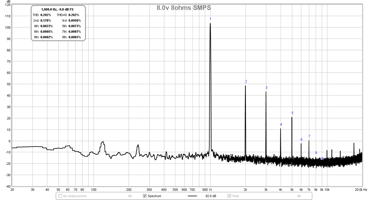
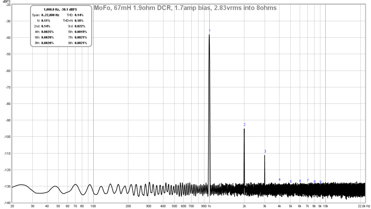
I know that there is a lot of praise for shunt regulators and it is used in the most critical applications like MM stylus pre-amps, etc. They are not the quietest technology though (ask Jan Didden) because you are trying to take 120Vrms down to below 50uVrms at 60Hz. Whereas the switch mode supplies moves the 60Hz out to about 400kHz or even 1MHz in some cases where it is beyond the audio band, and it is easy to make steep filter without using 120mF's of caps. Quiet PSU's are relative, as you only need to get below about -80dB and it is "silent" to the ears. An FFT tells a deeper story and quantifies how "black is the black"? Are there any FFT's of a shunt regulated PSU running of a mains trafo? Is the FFT baseline flat-as-a-board quiet down to the measurement instrument noise floor?
Just a note that the SMPS feeding a DC-DC step up, then a cap Mx, followed by a CRCRC is already mostly built into the design. You just need to add the external SMPS ($15) from a laptop and the $7 DC step up unit. The cap Mx and CRCRC is built in to this preamp and I think JPS64 has also added a CLC filter before the cap Mx. It is a very simple and robust PSU system that I have used on about 5 headphone amplifiers now and all of them measure dead flat relative to noise.
But if you want to use a linear shunt reg to power this preamp, that is fine. Just warning you that it will not measure as quiet.
Very interesting. One of the other claims for the shunt psu is that it has very low output impedance up to the 150 - 200 kHz range. Do you have any information about how your psu compares? Also, are you able to put the psu "in the box" or should part of it be in a separate box?
I have used SMPS and cap Mx with CRCRC in the most demanding Class A amps running between 1.2amps and 1.8 amps continuously through the cap Mx and double the current (3.6amps) through the DC step up.
The SMPS are rated for 4.6amps at 19v, the DC step up is rated for 10amps, if you add a 20 x 1000uF cap array, it will give it deep reserves for Class AB amps with low ESR of 3milliOhm. But for Class A, this is not needed as the current draw is steady and continuous. An ideal situation for a cap Mx. Even so, an IRFP240 can handlw 20amps peak, an IRF610 as used here can handle several amps, whilst the bias current is only 200mA max when running as headphone amp and maybe 30mA as a preamp.
Here is an example of the improvement in noise from switching from a traditional linear trafo/bridge/CRC to a pair of 24v 5amp SMPS connected in series for a dual rail +/-24v supply for a Pass M2 driving 8vrms into 8ohms. More in this thread.
With 400VA toroidal trafo and bridge/CRC:
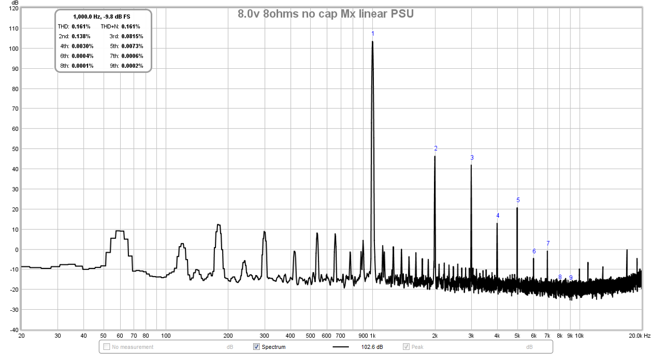
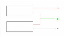
With two 24v 5a SMPS ($15ea) bricks:
I have put the SMPS, cap Mx, and CRCRC all in the same box and it works fine. An example is my Silicon Harmony SE Class A headphone/speaker amp as seen on display at a recent Head-Fi meet in Gaithersburg:

Last edited:
Do you sell only the cap multiplier?
You can download a variety of Gerbers for the cap Mx from this thread. The last one by Prasi is very compact and fits on 100mm square (magic price point for cheap PCBs) and is dual rail.
Juma's Easy-Peasy Capacitance Multiplier
If you don't need looks, just dead-bug it. 8 parts and they all solder to the legs of a MOSFET:
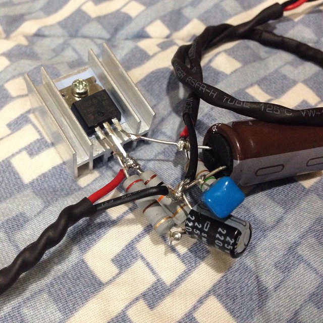
Last edited:
Sir would this brick power supply and DC to Dc work well with a dynamically changing class AB amp?
That’s a great question but the cap multiplier is getting off topic. Please ask again in the thread:
Juma's Easy-Peasy Capacitance Multiplier
Thanks,
X
... Here is an example of the improvement in noise from switching from a traditional linear trafo/bridge/CRC to a pair of 24v 5amp SMPS connected in series for a dual rail +/-24v supply for a Pass M2 driving 8vrms into 8ohms. More in this ...
SMPS in series ?
Attachments
Last edited:
GB Thread Started
I was asked to start a GB thread for this thread and keep technical discussions here.
GB thread:
http://www.diyaudio.com/forums/group-buys/315521-aksas-lender-preamp-40vpp-ouput-gb.html#post5261067
I was asked to start a GB thread for this thread and keep technical discussions here.
GB thread:
http://www.diyaudio.com/forums/group-buys/315521-aksas-lender-preamp-40vpp-ouput-gb.html#post5261067
SMPS in series ?
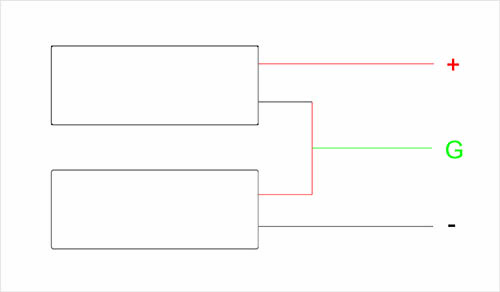
Yes, close. Not absolutely needed, but add some CRC filtering to clean up and give reserve for dynamics. I have used 9600uF//0.47R//9600uF or 22,000uF//0.22R//22,000uF with 0.1uF film cap bypass at output of CRC.
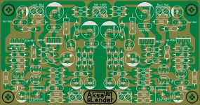
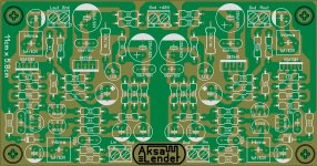
Hello.I made a stereo version -all parts throughhole- PCB.I hope its good.I replaced KSC1845 with 2N5551 (any disadvantage with this change?), added a led indicator,a 47ohm series output resistor and 2 RC networks at psu rail.What do you think?If anyone is interested i can post toner.pdf. xrk971 can you post LTspice.asc file?
Attachments
Last edited:
Hello.I made a stereo version -all parts throughhole- PCB.I hope its good.I replaced KSC1845 with 2N5551 (any disadvantage with this change?), added a led indicator,a 47ohm series output resistor and 2 RC networks at psu rail.What do you think?If anyone is interested i can post toner.pdf. xrk971 can you post LTspice.asc file?
Very nice! Thanks for making this, I am sure there are pdf transfer folks out there interested in this.
A few comments: the KSC1845 is a special transistor and the performance of this preamp depends on it. It's not that hard to find, quite common actually. I would make the pinout ECB to be compatible with the as-specified part and let people twist the legs of the 2N5551 if they want to swap. The label on Rout and GND are reversed. You changed many values of the resistors and coupling caps from what was shown in the original schematic, why? Perhaps label the components following the notation of the posted schematics. Else, a constructor will use the as-printed values on the silk and the preamp may not work as specified if values were followed.
Last edited:
Very nice! Thanks for making this, I am sure there are pdf transfer folks out there interested in this.
A few comments: the KSC1845 is a special transistor and the performance of this preamp depends on it. It's not that hard to find, quite common actually. I would make the pinout ECB to be compatible with the as-specified part and let people twist the legs of the 2N5551 if they want to swap. The label on Rout and GND are reversed. You changed many values of the resistors and coupling caps from what was shown in the original schematic, why?
I think its would be very help full if there were complete kit minus the chassis if you will available.
just a thought, this preamp looks amazingly good
")
Yes, close. Not absolutely needed, but add some CRC filtering to clean up and give reserve for dynamics. I have used 9600uF//0.47R//9600uF or 22,000uF//0.22R//22,000uF with 0.1uF film cap bypass at output of CRC.
thanks
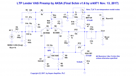
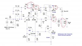
xrk971, this is the schematic i used to make the layout.i also attach the schematic with what i added.I corrected my layout.Is the schematic i used the final one?Are the values i used ok?
Attachments
Here is an example of a 0dB gain Class A amp driven by this preamp.
http://www.diyaudio.com/forums/pass-labs/313649-build-mofo-32.html#post5263537
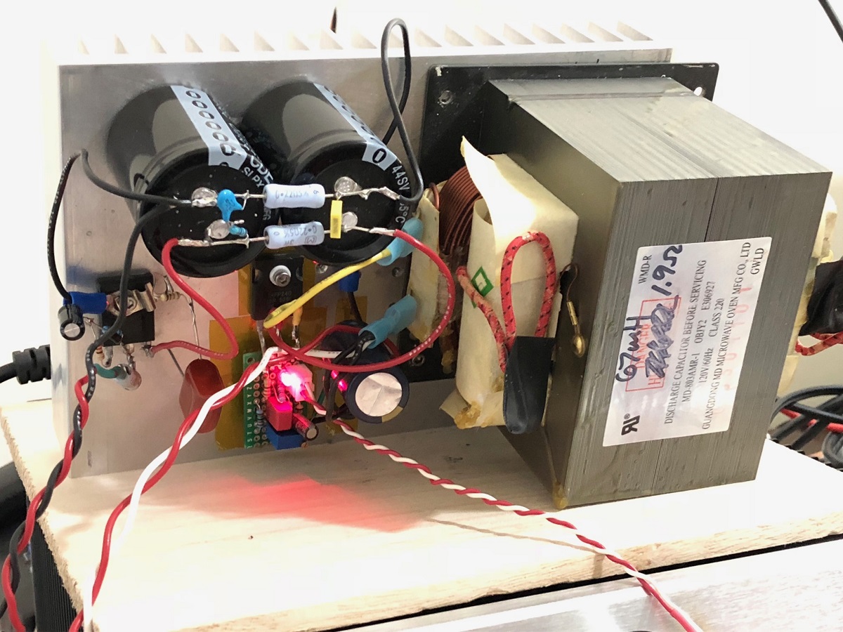
I just got an old 67mH microwave choke for it (free as it was a dead microwave I have been hanging on to for years) - sounds very nice.
http://www.diyaudio.com/forums/pass-labs/313649-build-mofo-32.html#post5263537
I just got an old 67mH microwave choke for it (free as it was a dead microwave I have been hanging on to for years) - sounds very nice.
- Home
- Source & Line
- Analog Line Level
- AKSA's Lender Preamp with 40Vpp Output