Looking at this logically, it would seem that NP does not use a snubber across the C/B of T5, and Cordell recommends a snubber at gate to drain, I'm inclined to leave the design exactly as it is...... unless Kean, Diego, Maty, or Paul can come up with a very good reason there is no requirement for two independent snubbers here.
This tangent started with a discussion on the phase lead capacitor and why it might affect the sound so much. I suggested it may be because the T5/M1 resonance interacts with the amplifier's compensation.
My point was never that the amp is unstable, it was that if you're looking for what may be affecting the sound, try looking here. What I said specifically is that the T5/M1 loop is not unstable, but it resonates because it's undercompensated.
So my focus has been on potential explanations for the affect of phase lead on sound, not about instability.
As for two separate RCs, Paul Bysouth corroborated that they have two different functions. In effect, they treat two different feedback loops. One being the T5/M1 loop (3.3k+47pF) and the other being the parasitic Colpitts oscillator feedback loop (47R+220pF).
Note that with a high Gm MOSFET, you increase the open loop gain of the T5/M1 loop. Also notice that for the Colpitts parasitic circuit to oscillate, the gate needs a low impedance path to ground.
Colpitts oscillator - Wikipedia
T5's collector impedance on it's own is very high, but in-circuit it is defined by the T5/M1 feedback loop, which is hindered in the way the Colpitts loop is. So I suggest that my RC may actually be the correct RC for curing high-Gm MOSFET oscillation in this circuit. I may be wrong, but that's what testing is for, isn't it?
Last edited:
Kean,
But it does not oscillation, either at T5/M1, or any where else.
I accept your sharp suggestion and Spice indicate it scotches the 5MHz oscillation at the gate, but in reality it's not needed.
I may experiment with >20S mosfets, but his is not a CFP. T5 is driving a source follower.
Thanks for your input, I am mindful of it and am constantly considering the options. I'm pretty sure where the spatial properties come from on this amplifier as it happens; it is a feedback quality.
Hugh
Last edited:
Just saying it might sound better
Now there is a thought! Thank you, I will ask X about it!
HD
Build preparation, or curiosity killed the Cat
Why "curiosity killed the Cat",
I did start the F6 long time ago, but never completed.
Here I like the concept that no un-obtainable (end of live) parts are used.
Also, when I understand correctly, the ALPHA 20 does not need a closed case, (due to self/auto bias) as where the F6 build does need a closed case.
So the F6 will have to wait.
Some questions and a status update.
Question(s):
1). C103 cap, Due to the limited size on the Alpha 20 board, a 1000uF capacitor will not fit, the max diameter for the C103 cap is 10 mm and the RM is 5 mm, this gives me a max of 470 uF 50 V (10 times the original of 47 uF (C103 is named C2 in the original AKSA schematic).
Now to the question, is the 1000 uF important or will any bigger cap as 47 uF do?
2). About the "Elna Audio SILMIC II" capacitors, better to select "Panasonic" or "Nichicon" when "Elna SILMIC II" are not available? (at least Conrad does not have these in there program)
Status Update:
Yesterday I started converting the BOM to a conrad.de order.
Reasoning: Mouser(Germany) does not have the "844-IRFP240PBF" available, will become available aug./sept. 2018
Stuff I have available:
Some pictures, from left to right:
Why "curiosity killed the Cat",
I did start the F6 long time ago, but never completed.
Here I like the concept that no un-obtainable (end of live) parts are used.
Also, when I understand correctly, the ALPHA 20 does not need a closed case, (due to self/auto bias) as where the F6 build does need a closed case.
So the F6 will have to wait.
Some questions and a status update.
Question(s):
1). C103 cap, Due to the limited size on the Alpha 20 board, a 1000uF capacitor will not fit, the max diameter for the C103 cap is 10 mm and the RM is 5 mm, this gives me a max of 470 uF 50 V (10 times the original of 47 uF (C103 is named C2 in the original AKSA schematic).
Now to the question, is the 1000 uF important or will any bigger cap as 47 uF do?
2). About the "Elna Audio SILMIC II" capacitors, better to select "Panasonic" or "Nichicon" when "Elna SILMIC II" are not available? (at least Conrad does not have these in there program)
Status Update:
Yesterday I started converting the BOM to a conrad.de order.
Reasoning: Mouser(Germany) does not have the "844-IRFP240PBF" available, will become available aug./sept. 2018
Stuff I have available:
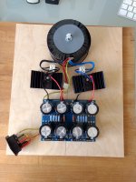
- A partially build diyAudio UNIVERSAL PSU V3 originally for a diyAudio Firstwatt F6 system (with a 2x18 Volt Torodiy 300 VA Transformer)
- Two Fisher SK 93 100 SA heatsinks ( 400 x 40 x 100 mm )
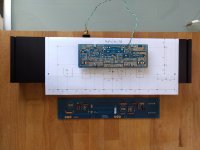
Some pictures, from left to right:
- The nice JP64 board with some mechanical parts and a 50 Volt 1000 uF Capacitor for C103.
- The "Aksa Lender P-mos Hybrid Aleph (ALPHA) Amplifier" board, on a diyAudio UMS printout, positioned in such a way that I can change to F6 board (to compare) on the Fisher SK 93 100 SA heatsink.
- The partial build F6 PSU
Attachments
Watchtmouse,
You are moving fast. 100uF 16v is all you need and not 1000uF 50v. That was my fault for over spec. I would use 220uF 25v if you have it. It doesn’t see anything higher than rails / 10 or 2.5v. There are nice Fairchild alternatives to IRFP. Some are mentioned in post 1. It doesn’t hurt to use big IXYS and leave option to run high bias for 4R version. Your F6 PSU is fine. Go forward then and don’t let the curiosity kill the cat watching the mouse! Panasonic FC/FM/FR are fine. Nichicon KA etc fine.
You are moving fast. 100uF 16v is all you need and not 1000uF 50v. That was my fault for over spec. I would use 220uF 25v if you have it. It doesn’t see anything higher than rails / 10 or 2.5v. There are nice Fairchild alternatives to IRFP. Some are mentioned in post 1. It doesn’t hurt to use big IXYS and leave option to run high bias for 4R version. Your F6 PSU is fine. Go forward then and don’t let the curiosity kill the cat watching the mouse! Panasonic FC/FM/FR are fine. Nichicon KA etc fine.
Watchmouse.
Here they have Nichicon KA.
Audiokondensatoren der Firma Nichicon //
TME Germany GmbH - Elektronische Bauelemente
(id2133)
And well sorted by Elna Silmic here.
Elna :: Electrolytics :: Capacitors :: Passive Components :: Electronic Parts :: Banzai Music GmbH
If you like to choose.
Regards.
Here they have Nichicon KA.
Audiokondensatoren der Firma Nichicon //
TME Germany GmbH - Elektronische Bauelemente
(id2133)
And well sorted by Elna Silmic here.
Elna :: Electrolytics :: Capacitors :: Passive Components :: Electronic Parts :: Banzai Music GmbH
If you like to choose.
Regards.
ALPHA Oscillation at 5MHz?
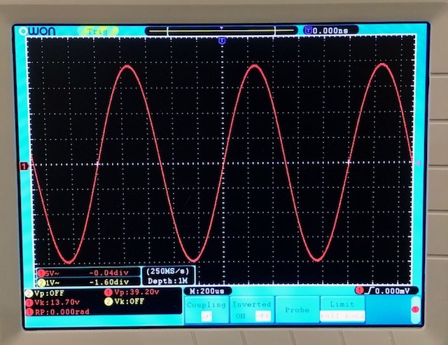
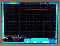
I hooked up a 8ohm 25w dummy load to the ALPHA 20, gave it 1kHz excitation to produce about 30vpp or about 14wrms. A good drive and equivalent to about as loud as it will be played at any reasonable speaker level.
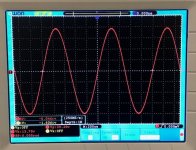
Here is the O-scope shot for 1kHz 29.6vpp into 8ohms, looks clean:

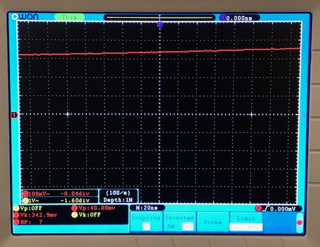
I then zoomed in to 20ns/div where 5MHz oscillation should show up, moved around from all time bases up and down on my OWON SSO 8192-V scope (100MHz 1Gsample/sec) and did not see any oscillation. Here is screenshot at 20ns/div, pretty much representative of the other timebases circa 20ns/div:
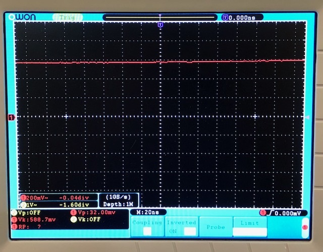
So I don't see any sign of oscillation on ALPHA 20 at a pretty hard drive. For the record, this is using 1206 SMT 22pF 5000v NP0 cap for C105 in schematic for production board.
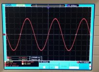
Edit, just took same data for BB, now at 39.2vpp into 8ohms or about 24wrms:
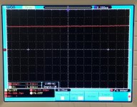
Here is the same drive but zoomed in on 20ns/div time base - and going up or down in timebase did not reveal any oscillation near 5MHz, and for the record, a 33pF 500v silver mica radial cap is used here for the compensation, with the recommended 220pF and 47R snubbers right at the D & G of the MOSFETs:
Also, btw, with zero input excitation, zooming into 5mV/div vertical and all timebases, revealed no oscillation at zero input.
Now there is a thought! Thank you, I will ask X about it!
HD
I hooked up a 8ohm 25w dummy load to the ALPHA 20, gave it 1kHz excitation to produce about 30vpp or about 14wrms. A good drive and equivalent to about as loud as it will be played at any reasonable speaker level.
Here is the O-scope shot for 1kHz 29.6vpp into 8ohms, looks clean:
I then zoomed in to 20ns/div where 5MHz oscillation should show up, moved around from all time bases up and down on my OWON SSO 8192-V scope (100MHz 1Gsample/sec) and did not see any oscillation. Here is screenshot at 20ns/div, pretty much representative of the other timebases circa 20ns/div:
So I don't see any sign of oscillation on ALPHA 20 at a pretty hard drive. For the record, this is using 1206 SMT 22pF 5000v NP0 cap for C105 in schematic for production board.
Edit, just took same data for BB, now at 39.2vpp into 8ohms or about 24wrms:
Here is the same drive but zoomed in on 20ns/div time base - and going up or down in timebase did not reveal any oscillation near 5MHz, and for the record, a 33pF 500v silver mica radial cap is used here for the compensation, with the recommended 220pF and 47R snubbers right at the D & G of the MOSFETs:
Also, btw, with zero input excitation, zooming into 5mV/div vertical and all timebases, revealed no oscillation at zero input.
Attachments
Last edited:
Parts selection
X thanks for clarifying, for now I will first build the 8R version, I might change over to the 4R version due to my KEF LS50 Speakers (nominal 8 Ohm, minimal 3.2 Ohms) at a later time (I do have some IRFP9240 for my F6 build)
Bangla H and Danny_66, thanks for the tips where to find components, both Bürklin (Fisher Heatsink) and TME (previous builds) have supplied me with components.
I also bought components from Banzai MUSIC before and I am currently ordering the Caps from them.
Happy listening
Bert
X thanks for clarifying, for now I will first build the 8R version, I might change over to the 4R version due to my KEF LS50 Speakers (nominal 8 Ohm, minimal 3.2 Ohms) at a later time (I do have some IRFP9240 for my F6 build)...
And the true sensitivity of KEF LS50 is only 83 dB.
Have you tried it with other class A amps? Which?
And the true sensitivity of KEF LS50 is only 83 dB.
Have you tried it with other class A amps? Which?
yep, pass F5T V3 with teabag boards, see Pictures of your diy Pass amplifier
Very nice AMP, the first AMP where I noticed that interconnects can make a difference, so very detailed even with my LS50's. But a big peace of Iron
")
KEF LS50 with 20-30w class A amplifiers | Stereophile.com
F5 Turbo V3 -> I think you need at least the BB52 at 4 Ohms.
I had a pair of Kef LS-50s that I used with various amps. Among them was my Pass Aleph 30, which as it's nomenclature indicates, is a 30wpc amp, in Class-A. The Kefs sounded ok but not spectacular with it. They liked a lot more power. In fact, the reason that I got rid of them was that they only ever sounded good with higher powered amps, and my amps are mostly low/mid wattage. They were my bedroom speakers and were eventually replaced by cheaper ELAC Uni-fi UB5s that actually sounded better with the amps I wanted to use in that system.
F5 Turbo V3 -> I think you need at least the BB52 at 4 Ohms.
Just now, the best La Wally record:
Catalani: La Wally (Complete) Tebaldi, Del Monaco, Cappuccilli, Diaz, Fausto Cleva; L'orchestre National De L'opera De Monte Carlo (1969), vinyl rip 24/192
DR Peak RMS Filename
----------------------------------------------------------------------------------------------
DR14 -0.78 dB -20.90 dB sideA.aif
DR14 -1.63 dB -21.27 dB sideB.aif
DR13 -1.51 dB -20.16 dB sideC.aif
DR14 -1.09 dB -20.36 dB sideD.aif
DR15 -0.67 dB -21.65 dB sideE.aif
DR15 -0.88 dB -21.82 dB sideF.aif
----------------------------------------------------------------------------------------------
Number of files: 6
Official DR value: DR14
Amazon.com: Customer reviews: Catalani: La Wally (Complete) Tebaldi, Del Monaco, Cappuccilli, Diaz, Fausto Cleva; L'orchestre National De L'opera De Monte Carlo
I have to raise the volume of my tweaked AV Marantz SR4500 (100watts at 0.1% distorsion) more than usual <- High DR records
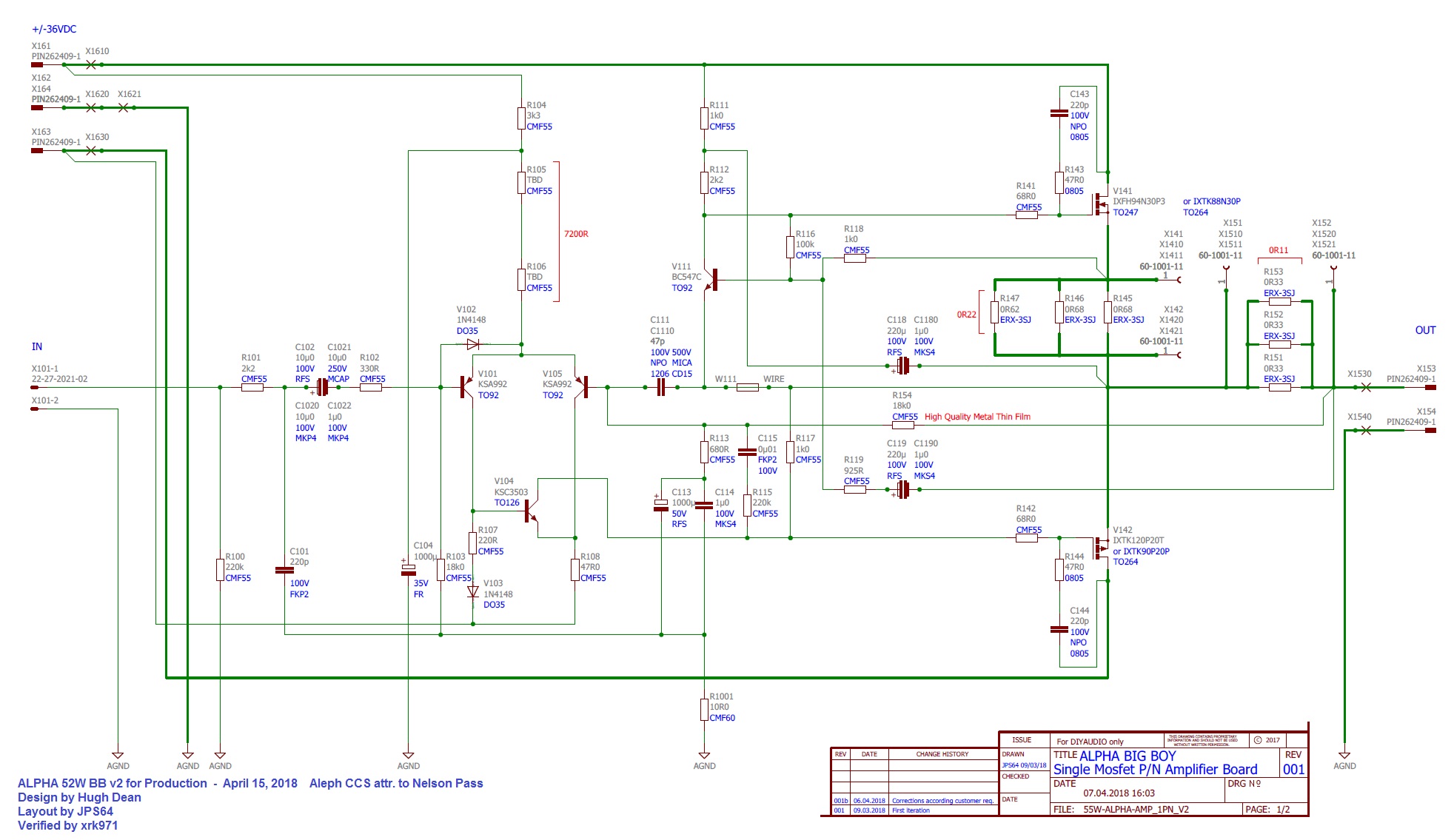
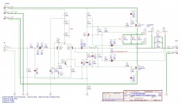
ALPHA 52W BB v2 Production Schematic & BOM
Here is the latest schematic for the BB amp that will go to production for the GB. I tried to update the BOM with as much info as I could recall based on my verification build and new info from recent posts - please let me know if there are errors on the BOM or if you have a question. The BOM is a .XLS file that has been zipped in order to be uploaded.
Schematic:
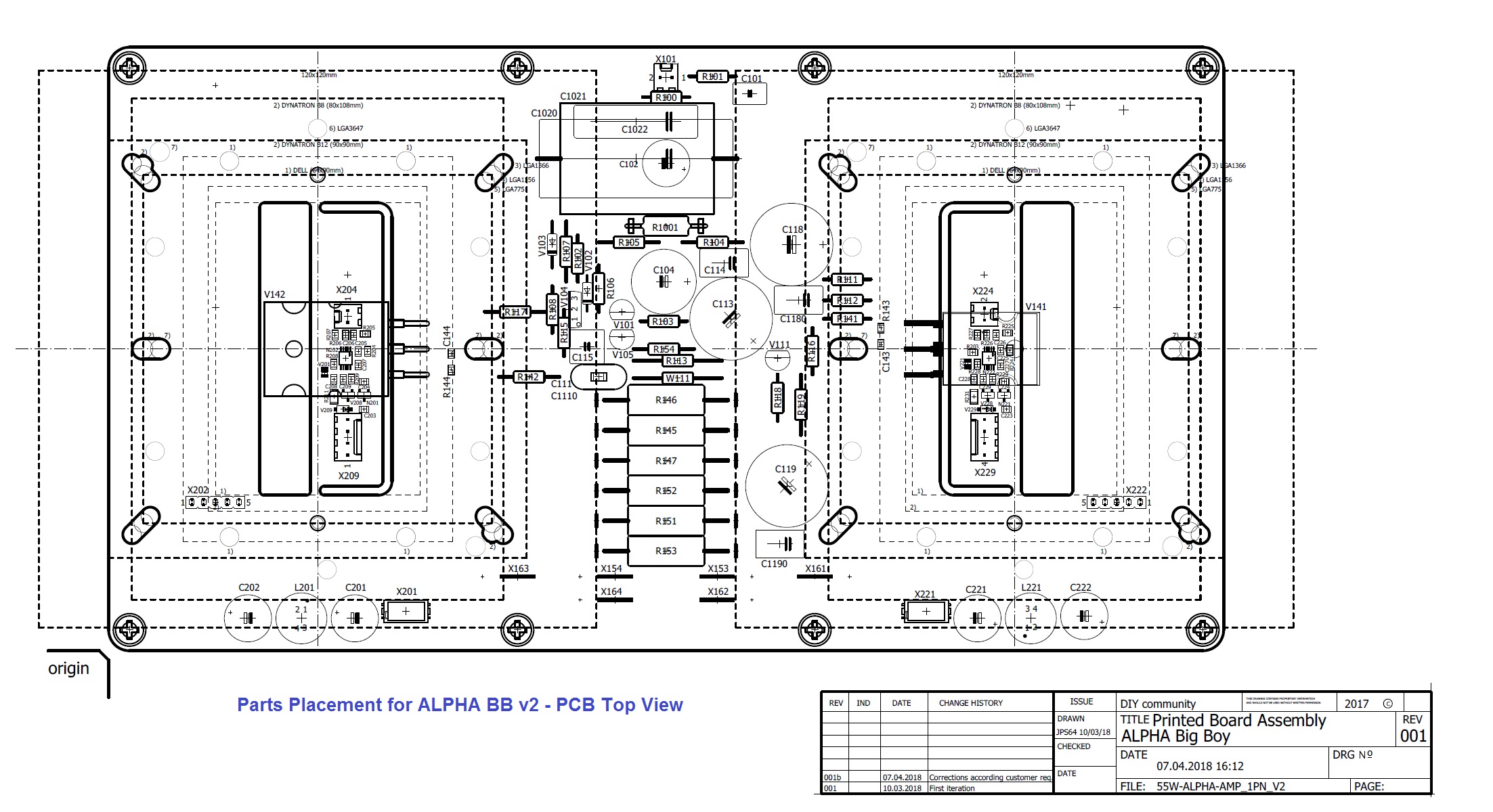
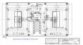
Parts placement on topside of PCB (board is 240mm x 130mm):
Here is the latest schematic for the BB amp that will go to production for the GB. I tried to update the BOM with as much info as I could recall based on my verification build and new info from recent posts - please let me know if there are errors on the BOM or if you have a question. The BOM is a .XLS file that has been zipped in order to be uploaded.
Schematic:
Parts placement on topside of PCB (board is 240mm x 130mm):
Attachments
Last edited:
Hey X,
The bom file says ‘invalid attachment’.
I just tested it again - the download works fine - it is a zip file of an .xls file.
Does the download happen and you can't open it?
Here it is as plain text, harder to read but info is there:
Code:
BOM for ALPHA BB v2 - Production,  compiled by xrk971 April 15, 2018,  Qnty is for 1 BB PCB, double order for stereo pair
All resistors 1% metal thin film 1/4W unless otherwise specified
Parts highlighted in yellow are optional if you want to make your own PWM fan controller.  Not needed if using COTS PWM controller.
Qty	Value	Package	PCB Label
6		PAD2MM	X1530, X1540, X1610, X1620, X1621, X1630  (Faston tabs)
3	0.22R TOTAL	ERX-3SJ (3W)	R145, R146, R147  (use for example 0.22R qnty 4 in series parallel) recommended Pan ERX metal thin film
3	0.11R TOTAL	ERX- (3W)	R151, R152, R153 (use for example 0.33R qnty 3 in parallel) recommended Pan ERX metal thin film
1	0µ01	C5B7.2	C115
1	1N4148	DO35-7	V102
1	1N4148	DO35-10	V103
2	1k0	CMF-55	R111, R118
1	1k0	CMF-55-13MM	R117
3	1µ0	C7.5B6	C114, C1180, C1190
2	2k2	CMF-55	R101, R112
1	3k3	CMF-55	R104
1	10R0	CMF60-ON-LUG	R1001
1	10u0	C22.5B7	C1022  (C102/1021/1020/1022 are all the same cap - pick your favorite input 10uF cap, 5.6uF is probably just fine)
1	10µ0	C37.5B19	C1020
1	10µ0	E5-10,5	C102
1	10µ0	MCAP250V10U	C1021
2	14k7	ERA6A	R204, R224
1	18k0	CMF-55+9MM	R103
1	18k0	CMF-55-13MM	R154  (Carbon Film or High Quality 1% Metal Thin Film like Dale)
5	20k0	ERA6A	R203, R206, R207, R226, R227
3	22-27-2021-02	6410-02	X101, X204, X224
2	22-27-2041-04	6410-04	X209, X229
2	22k0	ERA6A	R208, R228
2	34k8	ERA6A	R205, R225
1	47R0	CMF-55	R108
2	47R0	ERA6A	R143, R144 (0805 metal thick film snubber)
1	47p	C1206	C111  (tested 33pF silver-mica 500v is good, may possibly work as low as 15pF, listen for wide soundstage and no tizzy sound)
1	47p	CD15FD101FO3F	C1110
12	60-1001-11	60-1001-11	X141, X142, X151, X152, X1410, X1411, X1420, X1421, X1510, X1511, X1520, X1521
1	68R0	CMF-55	R141
1	68R0	CMF-55-13MM	R142
1	100k	CMF-55	R116
1	100µ	E7,5-16	C104
1	220R	CMF-55-13MM	R107
2	220R	ERA6A	R209, R229
1	220k	CMF-55	R115
1	220p	C5B4.5	C101
2	220p NP0/C0G	C0805	C143, C144  (tested with Wima 220pF 1000v FKP radial - it's an important snubber cap as it keeps IXYS from self-destructing)
2	220µ	E7,5-18	C118, C119
1	330R	CMF-55	R102
1	6k8	CMF-55+9MM	R105
1	400R	CMF-55	R106 (R105 and R106 need to add up to 7200R) this eliminates pot in V1
1	680R	CMF-55+9MM	R113
1	925R	CMF-55-13MM	R119
1	220u 25v	E7,5-18	C113 (220uF 25v should be sufficient, any good brand like Pan FC/FM/FR or Nichi KA or Elna Silmic ok)
1	BC547C	TO92-CBE	V111 (optional, match Hfe btwn left/right channels by 1% for same bias setting)
1	IXFH94N30P3	TO247-XRK	V141 (no matching needed - same tube helpful)
1	IXTK120P20T	TO264-XRK	V142 (no matching needed, same tube helpful)
4	KFH-M3-18	KFH-M3-18	X2041, X2042, X2043, X2044
2	KSA992	TO92-ECB	V101, V105 (match Hfe within 1% in LTP for low DC offset drift with temp; optional, match within 2% for left right balance)
1	KSC3503	TO126V	V104 (optional, match Hfe within 2% for same left right balance)
12	M3	M3MM2-GROSS	X2001, X2002, X2021, X2022, X2051, X2052, X2053, X2054, X2055, X2056, X2057, X2058
6	PIN262409-1	62409-1	X153, X154, X161, X162, X163, X164
1	WIRE	CMF-55+9MM	W111
1	PWM Fan Controller	COTS prebuilt PCB	for example, [url=https://www.ebay.com/p/12v-PC-CPU-4-Wire-Fan-Temperature-Control-PWM-Speed-Control-Module-W-Alarm/837831180?iid=201914727060&chn=ps]12v PC CPU 4 Wire Fan Temperature Control PWM Speed Control Module W/ Alarm | eBay[/url]

Parts below are for PWM controller and optional
2		FE05-1	X202, X222
2		MA05-1	X203, X223
2	0µ1	C0805	C209, C229
2	0µ01	C0805	C205, C225
8	1µ0	C0805	C203, C204, C206, C207, C223, C224, C226, C227
2	RR264M	SOD123	V209, V229
2	Si2302	SOT23	V208, V228
2	TC665	MSOP10	N202, N222
2	TS4148RY	V0805	V201, V221
2	MCP1700T-5002E/TT	SOT23	N201, N221
2	MICROMATCH-6	MICROMATCH-6	X201, X221
2	NP	C0805	C208, C228
4	1500µ	E5-10,5	C201, C202, C221, C222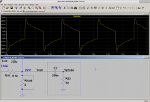
2 7447231332 WE-TIF L201, L221As I said, the resonance (NOT an oscillation) is nearly undetectable. A sine wave test is the weakest possible test for finding it. A sine wave has no 5MHz content, and even if this wasn't a class A amp, the switching transients wouldn't contain much either.
You need a square wave generator with 10nS or so risetime, and you might be able to see it if you zoom in on the root of the square wave, but probably not.
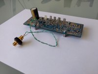
Use a 220p/50ohm HP filter like in the image.
You need a square wave generator with 10nS or so risetime, and you might be able to see it if you zoom in on the root of the square wave, but probably not.
Use a 220p/50ohm HP filter like in the image.
Attachments
- Home
- Amplifiers
- Solid State
- Aksa Lender P-MOS Hybrid Aleph (ALPHA) Amplifier