Hi, heatsink, well I tried various suggestions e.g. Checked heat was being distributed evenly by copper spreader, slightly cooler on the outer sinks but not by much. Tried removing sections and just using two with each mosfet connected to one each. Sinks became too hot to touch after a very short time. Using a Fan solved the problem, so I guess these sinks are just not suitable for use without a fan. I will look at other options. Using CPU coolers with fans seems to be a good solution, just wanted passive cooling really.
Regards
Alan
Regards
Alan
If you copy Pass simple circuit in simulation, does the simulator give respons like he measured for the Vishay/IRF P9240 fig. 13 and fig.14 ? Or does the model use the original/ideal better behaving part ?
http://www.firstwatt.com/pdf/art_mos_test.pdf
http://www.firstwatt.com/pdf/art_mos_test.pdf
Why amplifiers fail!
Off topic
Talking about heatsinks, heat, class A... I just read:
Why amplifiers fail!

Off topic
Talking about heatsinks, heat, class A... I just read:
Why amplifiers fail!
Electrolytic capacitors: useful lifeIn the vast majority of cases this is usually down to the failure of either output or driver semiconductors or electrolytic capacitors. In particular heat is the enemy of such devices and poor layout by the designer is often a contributary factor. For instance a number of manufacturers mistakenly locate electrolytic capacitors alongside heatsinks or power resistors. An average quality 85C capacitor probably has an estimated lifetime of 3000 hours at that temperature. This is generally accepted to double for every 10 deg C reduction in temperature.
In a well known Class A amplifier from the 1980's the heatsink is happily running at just over 65C with several capacitors within a few mm of this meaning lifetime is probably 12000 hours or so before they are outside the specified tolerance. If the amplifier is used for 3 hours daily then 12000 hours equates to about 11 years before such components are nearing end of life. Of course that is an extreme case afflicting only a few particular models...

Offset problem, as mentioned previously I have about minus 15mV offset on both channels. I understand that this is not a problem, but I was looking at ways to get it nearer zero if possible. I replaced R105 pot with a 1.2k resistor , found offset to be the same. Changed the 1.2k for a 1.3 k and the offset was very similar.
I can reduce the offset to zero by reducing the value of R106 from 220 ohm to 180 ohm. This stays constant from cold to hot. Is hanging R106 value detrimental in any way, or am I just being too fussy.
Regards
Alan.
I can reduce the offset to zero by reducing the value of R106 from 220 ohm to 180 ohm. This stays constant from cold to hot. Is hanging R106 value detrimental in any way, or am I just being too fussy.
Regards
Alan.
Yes, that unfortunately confirms my suspicion hereHi, heatsink, well I tried various suggestions ... Sinks became too hot to touch after a very short time. Using a Fan solved the problem.

Allan,
You have fixed the offset but you have changed the loop gain of the amp increasing distortion and altering stability. The best way is to increase the 'pot from 1k2 by 400-500 ohms to 1k5 or more. Best not to change 220/100 LTP arms because the compensation of the amp might need reviewing to maintain the stability.
HD
Last edited:
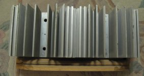
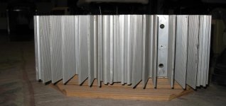
Heatsink not enough to be big & heavy, surface area and weight combination play a big factor to be a good cooler device.
Your heatsinks fins are not enough to compare to the whole heatsinks weights, the other problem when the two heatsink next to each other they create a thin tunnel between the fins with limited air movement between the fins.
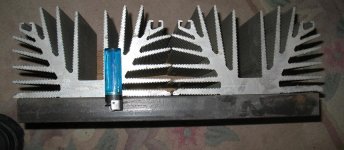
If you put two piece 8X8Cm fans under the sinks with very low speed (no noize at all) that would do the job. In that case, you have to add some feet to elevate the heatsinks (to create some rooms under the heatsinks for the fans) Something like my picture.
Your heatsinks fins are not enough to compare to the whole heatsinks weights, the other problem when the two heatsink next to each other they create a thin tunnel between the fins with limited air movement between the fins.
If you put two piece 8X8Cm fans under the sinks with very low speed (no noize at all) that would do the job. In that case, you have to add some feet to elevate the heatsinks (to create some rooms under the heatsinks for the fans) Something like my picture.
Attachments
Thank you Hugh for your swift reply. I'm sure you must get fed up of answering questions to DIYers like me. Thank Heavens there are people like you, XRK, etc that donate time and effort to helping us.
I will revert to the values on the diagram and not worry about the slight offset.
Regards
Alan.
I will revert to the values on the diagram and not worry about the slight offset.
Regards
Alan.
Hi BRN,
Hugh was actually talking about Danny_66’s low impedance amp request with 2.3amp bias that is stable into 2.7ohm load.
For Alpha 20, I am confident now it needs no pots at all. Just make R115 a 1050 ohm resistor. Probably 1000+47R is fine.
xrk971,
Thank you for the clarification. Looking forward to building the amp.
Thank you,
Brad
Can you please show schematic or sketch of the setup? What is the purpose of the DC-DC converter since you are using a linear trafo and rectifier?
Hum usually a ground loop as DC converters are running close to 400kHz. Usually I have a cap multiplier after the DC converter followed by a CRCRC with snubber to filter.
To simply filter DC converter noise, usually an LC filter is used. There was a reference earlier in thread by JPS64 to to DC step up filters.
Can you please show schematic or sketch of the setup? What is the purpose of the DC-DC converter since you are using a linear trafo and rectifier?
Hum usually a ground loop as DC converters are running close to 400kHz. Usually I have a cap multiplier after the DC converter followed by a CRCRC with snubber to filter.
To simply filter DC converter noise, usually an LC filter is used. There was a reference earlier in thread by JPS64 to to DC step up filters.
It's just something I had in my hands so I can power and adjust fan without any external psu's. So powering only fan with that.
Main trafo-> one rectifier's positive and negative leads->dc-dc step up/down->fan.
Oh if it’s for cooling fan, try a linear LM317 (With 1uF film cap bypass input and output legs) and use that to adjust fan. Or use 7812 and 100R 1W in series to drop voltage and keep quiet.
Thanks! Is there any way to filter down noise I have now with dc-dc reg? I can't get about anything but basic caps and resistors locally, so I have to order everything and always pay shipping and wait for a week. I'll get whats needed on my next order, but that will be B.B's part order, so it'll take some time.
Try a 1000uF // 10R (3W) // 1000uF // 10R (3W) // 1000uF - CRCRC, be sure to put R’s on negative or GND pins as well (need 4 resistors total) as noise travels down local GND pin as well. Caps can be 220uF to 1000uF, R can be 3.3R to 10R. Add 330pF and 51R snubber between positive and negative of DC step down.
Hi Hugh,
The ltspice schematic for low voltage and high current you attached in this post
has it's rail voltage at 24v.
Can you check if this is the correct schematic ?
Regards,
Danny
The ltspice schematic for low voltage and high current you attached in this post
has it's rail voltage at 24v.
Can you check if this is the correct schematic ?
Regards,
Danny
I just got word that the B.B. boards are done and getting packed for the DHL cargo plane. Should be here in a few days. Big 400VA 25v Trafo is here, CRC PSUs are a go, IXYS MOSFETs and PWM SMTs ordered, Vishay Dale CMF resistors ordered, CPU cooler heat pipes are ready, a BB beta build session coming to a workbench near you soon
I think they are 240mm x 130mm.
I think they are 240mm x 130mm.
Measured 100 devices for hFE with my hot-rodded tester. Will have a good batch of matches.
BK
For any interested ALPHA builders, I have some extra matched* devices that are available just for the cost of USPS shipping in a padded envelope. I made a google doc, so just claim what you're interested in and I'll PM you in about a week for next steps. Max 8 pieces/amp.
BK
*Measured Vbe and hFE at room temperature with an upgraded "transistor tester" using best practices. Easy peasy.
ALPHA_KSA992FBU_matched - Google Sheets
- Home
- Amplifiers
- Solid State
- Aksa Lender P-MOS Hybrid Aleph (ALPHA) Amplifier