Awesome. It’s a quick build if you have all parts. Do you have the UMS heatsink? That made things go much much faster.
I have the Dell heatpipe/sinks. I need to order the big input films and a few mills for the 0.33, and 0.12 resistors.
I have some substitute components that I'll likely use to get first sound.
Power supply is ready, I think I got some good matches for the ksa992's ready. I need to get the 9240s and 240s Vgs measured.
I can't read the schematic in the Pass article for measuring vgs, but I think I can discern what's needed.
F6 PSU with CL60’s works very well to reduce hum for linear trafo application. However, I am not sure if it is compatible with the DC outputs of the dual channel cap multiplier here. I am thinking my problem may be two parts: use of too small as snubber film cap (0.1uF vs 1uF) and the ground from the amp needs to go back to the star hub vs the GND on the CRC.
One thing I learnt from Keantoken and AndrewT, current just needs to pass from one cap to next cap and so do grounds need to pass the same currents in the return line. Break this chain, you will have problems...
Also I feel input cap on your cap Mx is too low. Juma didnt specify 47000uF arbitrarily. If not 47kuF, somewhat higher /closer value must be warranted.
Could you remove the CRC and see if CMX works alone satisfactorily with a trafo and regular bridge rectifiers, just as was intended design? I think you built this CMX before too with very satisfactory results with a trafo, if memory serves right. The regular set up.
Also see if you can cut the signal gnd trace and place HB resistor in the path as you said its a star grounded amp pcb.
Thanks, Gaborbela. If you want to post high resolution paint graphics - the key is to create a basic image with sufficient resolution as the background. I think you may have selected some default low resolution image. We can easily upload a 1200x900 pixel image into DIYA servers. Even bigger if you want. Limited by 1.76Mb file size. You can go to resize and check pixels and enter sone number like 1200 or 1600.
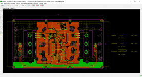
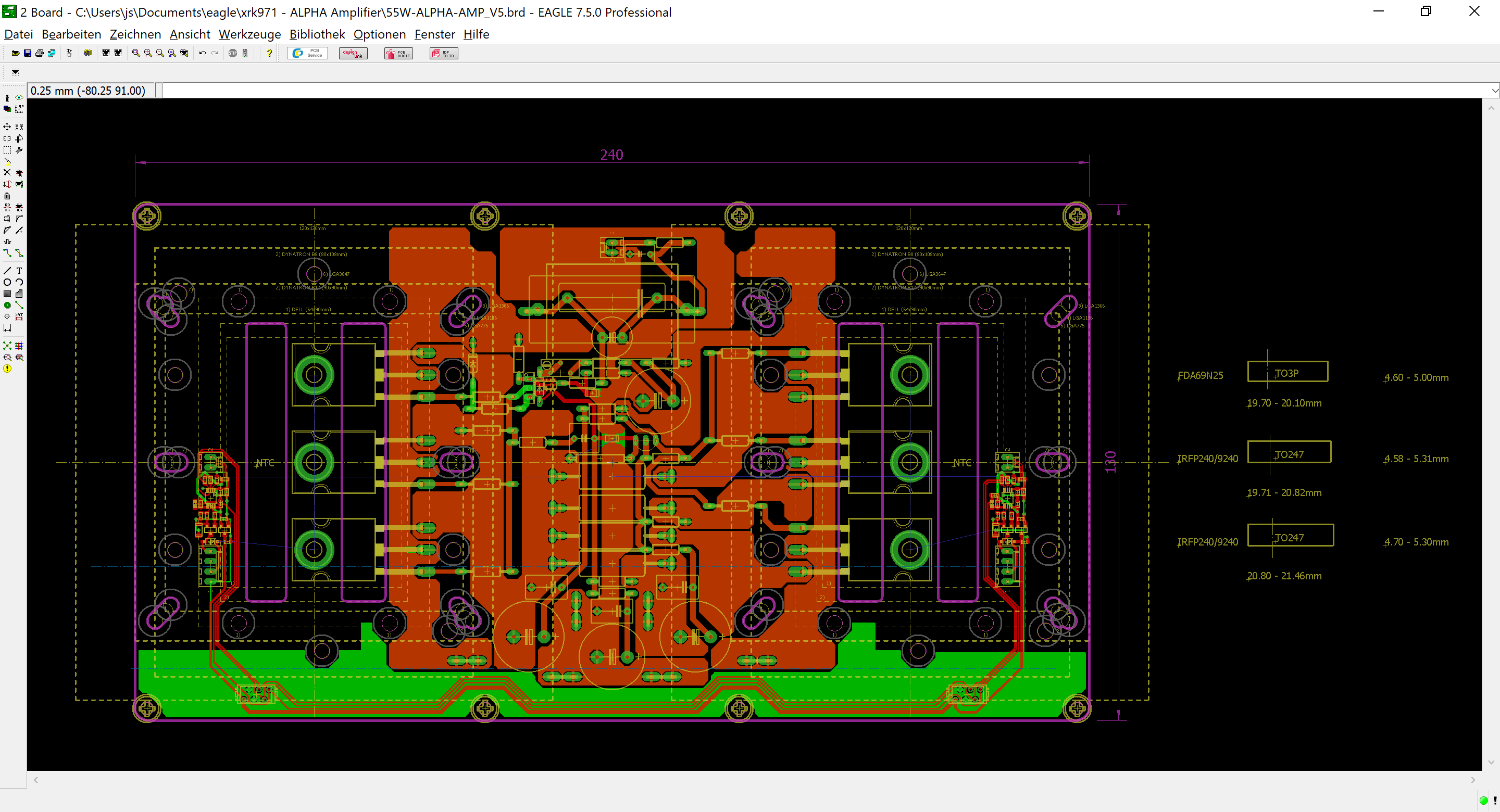
Thanks for sending me the layouts. I can post them for you but I think I am going to wait for JPS64 to finish the layout and just buy the PCB.
Thanks for sending me the layouts. I can post them for you but I think I am going to wait for JPS64 to finish the layout and just buy the PCB.
Thanks, Gaborbela. If you want to post high resolution paint graphics - the key is to create a basic image with sufficient resolution as the background. I think you may have selected some default low resolution image. We can easily upload a 1200x900 pixel image into DIYA servers. Even bigger if you want. Limited by 1.76Mb file size. You can go to resize and check pixels and enter sone number like 1200 or 1600.
Thanks for sending me the layouts. I can post them for you but I think I am going to wait for JPS64 to finish the layout and just buy the PCB.
X I draw my layouts with paint, to get the good quality picture you must save it to your computer and open it with paint also you have to print it out from there! I have to scale it down when I print it our because it is too big! I use Windows XP's paint because it has more option to work with. But I can open it with Windows 7 paint and perfect.
I did correct the layout if someone wants to use passive monster heatsink this layout is perfect for that. Anyway, if someone needs it (I will use these when I build the BigBoy) I have it already! Please PM for so not to mess up the forum with amateur layouts. Those who use software they can create professional layouts at no time compared to draw with hand. I have Sprint but too complicated used me. I got use to it to these, I draw my layouts more than 10 years these way.
BB on progress but very very busy with writing big technical specification for my business and I´ve to solve before end of the week some cabling manufacturing problems.
Status: analog part so far ready but complete new fan electronic added (based on TC665 using standard NTC). I´ve to build first a mechanical mockup to verify heatsinks mounting options.
Sorry that you´ve to wait but no problem ALPHA 20W is good practice.
JP
Status: analog part so far ready but complete new fan electronic added (based on TC665 using standard NTC). I´ve to build first a mechanical mockup to verify heatsinks mounting options.
Sorry that you´ve to wait but no problem ALPHA 20W is good practice.
JP
Attachments
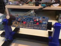
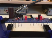
Was able to get a good bit of the first board stuffed and soldered during my lunch break.
I had to place one of the mks caps on the bottom as what I had on hand was a bit big. The 1uf wima's I had on hand are a touch big as well, but I think I can get them on with no fuss.
Resistors are Takman REY, Dale CMF, and some Vishay 2% RL(cmf). I may have to parallel a few resistors for the 0.22, and 0.12 positions to get it up and tested. I forgot to order the mills for those spots.
Cheers,
Gable
Attachments
WOO HOO!! I received my boards today
Thanks X!
They have a solid, luxurious quality feel to them.
Amazing job JPS64")
Nice!
They are _very_ nice boards, JP64 you did a wonderful job!
Yes, +1 to JPS64 for a superb design on the layout. The 52W Alpha also looks to be stunner, and looks unlike any other Class A amp I have seen on DIYA or otherwise. Nice job JPS64. 
I assume the Alpha 52 will also have numerous vias and of course, we will make it in 2mm thcik FRP and double thick copper with ENIG finish.
I assume the Alpha 52 will also have numerous vias and of course, we will make it in 2mm thcik FRP and double thick copper with ENIG finish.
I have the same one - $12 on Amazon. I also have an old-school Panavise which is nice when you need to apply some force to the board.
Yup!
http://a.co/iLJNw4b
I have a panavise as well, this little one from Amazon though really works well for most boards.
The panavise is nice for heavier stuff certainly.
Looks like I was wrong on the trimmers on the BOM.
I ordered:
3296W-1-202LF Bourns Inc. | Potentiometers, Variable Resistors | DigiKey
3296W-1-104LF Bourns Inc. | Potentiometers, Variable Resistors | DigiKey
And I think we need:
3299Y-1-104LF Bourns Inc. | Potentiometers, Variable Resistors | DigiKey
3299Y-1-202LF Bourns Inc. | Potentiometers, Variable Resistors | DigiKey
X, JP, et all, can you confirm the above?
I think I can bend the center pin to reach.
I bent my pins. Don’t worry about it as long as values correct.
On LTP set trimmer to 1050R before installing.
On Aleph CCS use either trimmers set to nominal value of fixed resistors but not trimmer and resistor. Nominal values should be pretty good but trimmer allows precise adjustment of Aleph CCS action which is checked with 1kHz sine wave and two AC voltmeters.
- Home
- Amplifiers
- Solid State
- Aksa Lender P-MOS Hybrid Aleph (ALPHA) Amplifier