I think it was about about 65x2= 130 watts of consumption in stereo, with 18.9 watts by channel. I was wrong?we are nudging around 30% at full power for the ALPHA20 and a little more for the BB.
Sorry, I have a suspense in maths
 18.9/65 = 29%.
Tierra trágame = Earth swallow me
Last edited:
Hi X,
Its the calibrate by ear thing over a sometimes non documented speaker domain response and SPL level i disagree, have no problem follow to have a amp act theoretical as a short piece of copper wire, then covered band width from input to output will help and as you point out numbers as 300kHz and up is probably good numbers to save a bit on phase, but out of those dozen of amps then what about your VSSA amp which should also perform fine up there or be maybe be even more than the mentioned 300kHz bandwidth so can i ask if your conclusion for that one also kill the best spatiality and 3d depth of soundstage.
Some visual numbers is below in red trace that simulate a smooth 20Hz-20kHz speaker domain with a declining curve as frq goes up, when that isolated perfect minimum phase domain is added a 2nd order low pass up at 300kHz we get the blue trace which is just a very little bit visible in amplitude domain up above 20kHz point and move few deg in audio bands phase domain. Myself had been there with exercises for phase correction in DSP that move phase a little bit or enormous in either advance or into more lag to try to kind of correct for what a limited recording chain could be responsible of added phase distortion under recording process, and also down at low end have tried many of imagined phase corrections to clean up what transformers in old tube recording gear can be responsible for or what tens of capacitors into SS mixers can add up. Sometimes thought in those exercises aha here is something, but always down the road it turned out over time than its either track dependent or ear fatigue over time. Best results for foot tapping and a smile i had are when acoustic domain is corrected to have a real minimum phase behavior which mean whole system chain is inside loop and corrected for so it ends a same impulse/step response as its synthetic target textbook will dictate and a system amplitude response something in area or close to those JBL studies, and guess why that is so good a acoustic target curve is that more or less many pros have that one dialed in when producing our material. Now note if AKSA is right that some NFB amps is too slow in VHF phase domain that when amp sits inside loop of acoustic corrected domain we get that distortion corrected too and probably the reason why speakers as Beolap 90 and Grimmaudio LS1 using digital amplifiers don't sound as they miss anything there, if you walk into a shop and get a listen. Also real speakers bandwidth seems limit any real square wave above 6kHz area to happen and worlds probably most used source material is filtered a low pass 96dB/oct or more at 22kHz.
Hi Byrtt,
I know you love to reverse-engineer an approximate phase response based on an idealized frequency response that has been fitted with a curve. It's a great technique to get insight into how things in the acoustic domain work. But in the case of an amp, you can't do that: there are traces, wires, parts, etc that all have parasitic capacitances, parasitic inductancs, frequency dependent resistances and capacitances, etc. Furthermore, there are finer effects of active device transconductance and beta. That's why we use comprehensive simulation tools like LTSpice, and even then, the models are incomplete - but you get a sense of the frequency response and phase response, and inherent harmonic distortion spectra. Take for example the simulation that Danny provided a few posts back based on Aksa's model of the Alpha 20. Here we can see the frequency response and the phase. It's not going to follow the REW-derived minimum phase from inversion (see how those purple traces of phase are non-monotonic? That's the pF-level effects in a complex system at play):
Regarding why we use the ear to tune the comp cap at pF levels. There is a difference between a 47pF comp cap and 10pF comp cap - trust me (and others here on this Forum) - we have heard it, or felt its destructive power when it is not big enough and the outputs get smoked with oscillations. Like Aksa said, you make it big enough based on sims to avoid oscillation. Then listen to the sound as you make it as small as possible before hearing a tizzing sound. You can also use an O-scope and observe the onset of osciilations and back off by increasing value. Most people don't have an O-scope which is why we suggest listening with your ears. It can pick up abberations in phase and mild oscillations even.
And if you don't think that we can hear usec delays in signals (especially above 6kHz), look for scientific publications on the human pinna and sound localization. The pinna is the earlobe, and in tests where the pinna was flattened (those mm level folds removed), the sound could not be localized.
In this article studying the localization of sound with simulated castings of pinna attached to microphones, they found that indeed the localization capability of the pinna resides in the 2usec to 300usec range. That's 500kHz to 3.3kHz and this is why pF's of compensation in circuit matter. You can definitely hear it (the phase) even though our ears are bandwidth limited to 20kHz (which is the low pass filter you like to always show on those reverse-engineered graphs). Again, frequency response bandwidth does not dictate the resolution at which phase can be discerned. Phase can be measured arbitrarily small (limited ultimately by Heisenberg's uncertainty principle at the quantum level).
https://pdfs.semanticscholar.org/a4ce/98ea97ade43618bab07cd017ef8f0ac34f5c.pdf
Last edited:
Hi X,
Thanks explain details for complex RLC parasites in amp design, can see direction it takes then that it doesn't matter if amp end up as a smooth as possible a minimum phase device from input to output and probably one point where we disagree so far but its also diy isn't : ) about the less phase lag claimed for your favorite amp builds in HF area you never answered about if that high bandwidth probably hated more or less by now VSSA amp also kill the best spatiality and 3d depth of soundstage.
As told for own exercises changing phase that reach inside audio band is audio able so its not necessary tell me to trust you and other here that changing phase slope relative to amplitude as frq goes up inside audio band using ear is audio able, its the non documented smooth slopes where you are and deviation from minimum phase behavior that get your method and probably also sound to stand out in my view.
That 20kHz 2nd order low pass is not to simulate ear band width its to simulate and cut out you end up in a real speaker and can not hope for much more there, but now after you reminded that ears also limit there we can then add a 1st or 2nd order more can't we : )...even though our ears are bandwidth limited to 20kHz (which is the low pass filter you like to always show on those reverse-engineered graphs)...
Well if there isn't any amplitude then there isn't any phase, but okay okay good enough points but for one more time i say useable band width for recording chains and reproducing chains that produce our material we probably end up so narrow limited a band pass that it end be so close to a real minimum phase device that don't you think it deserves we reference system to be close to a real minimum phase domain behavior so in play back we can be close hear what the piece of art is about that was mixed....Again, frequency response bandwidth does not dictate the resolution at which phase can be discerned. Phase can be measured arbitrarily small (limited ultimately by Heisenberg's uncertainty principle at the quantum level)...
Hi Danny,
I think you posted the process to safely lower the ALPHA20 gain, but of course I can't find it
I'd like to get down to 15-20 dB gain, if its not to much trouble could you run one of your fabulous simulations or point me to your posts? Thanks.
Much appreciated,
Vunce
I think you posted the process to safely lower the ALPHA20 gain, but of course I can't find it
I'd like to get down to 15-20 dB gain, if its not to much trouble could you run one of your fabulous simulations or point me to your posts? Thanks.
Much appreciated,
Vunce
Vunce,
I linked to the summary from post 1.
http://www.diyaudio.com/forums/soli...id-aleph-alpha-amplifier-166.html#post5400230
I think change R111 to 2k2 gives about 21dB gain.
I linked to the summary from post 1.
http://www.diyaudio.com/forums/soli...id-aleph-alpha-amplifier-166.html#post5400230
I think change R111 to 2k2 gives about 21dB gain.
Thanks X.
Just a resistor change, no capacitor also, correct?
The shunt cap needs to be at least 56uF, but I think you have a 1000uF so no worries.
No, Vunce, just the resistor...... you can reduce the cap if you want, but it won't make any difference to the sonics.
The formula for gain is (Rfb+Rsh)/Rsh.
So, for 22k Rfb and 2.2Rsh, we have 24.2/2.2 = 11
You then take the log of 11, which is 1.0414, multiply it by 20 and you have 20.83dB, 21dB roughly just as X said.
This is one proviso here. As you are reducing the gain, you are increasing the loop gain of the amp, that is, the ratio of open loop gain (max gain with no fb) over closed loop gain (nominal gain set by the fb resistors). When you increase loop, it's a good idea to examine the lag compensation values of the amp, and as has been identified in this thread, this is a bag of worms, quite the harded aspect of amp design. Generally you increase the compensation because there is more global fb now.
In this amp I suggest a single 22pF from emitter of the CCS controlling transistor, V121 BC547C, to the base of the fb transistor on the Long Tailed Pair, V102 KSA992. I do not believe we need to change this; a while back I'd addressed this in some detail but should do it with more explanation.......
Thanks for the post, and the PM, and for building the ALPHA!
Hugh
Thank you sincerely, Jean-Paul.
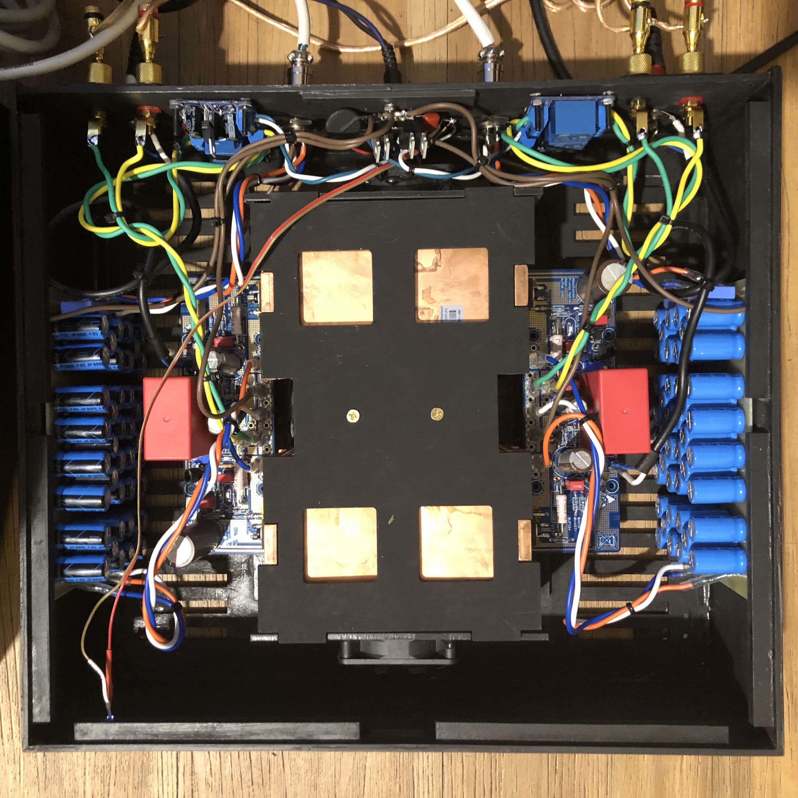
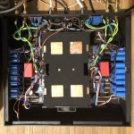
Your professional input is hugely appreciated. This brings this product to better than most commercial amps, particularly if people create a high quality enclosure. The cooling system is fuss free, quiet, and incredibly innovative and your infrastructure around it keeps it completely protected.
Hugh
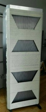
Finally got my Alpha 20 up and running, it's been just about an hour now, but the first impression was very balanced detailed sound , and the amp obviously has its own sweet signature.
I was expecting some noise or hum since i m running it with laptop SMPS but surprisingly no noise no hum whatsoever which made me even happier.
I will post more detailed pics later. had to post this before i go out.
Thanks to Hugh, X and JP.
, and the amp obviously has its own sweet signature.I was expecting some noise or hum since i m running it with laptop SMPS but surprisingly no noise no hum whatsoever which made me even happier.
I will post more detailed pics later. had to post this before i go out.
Thanks to Hugh, X and JP.
Attachments
- Home
- Amplifiers
- Solid State
- Aksa Lender P-MOS Hybrid Aleph (ALPHA) Amplifier