Akabak noob here - has anyone successfully/accurately simulated a downward-firing subwoofer? I'm thinking of a box with the woofer (and vent(s) if any) on the bottom surface, supported ~100mm from the floor by a leg near each corner.
My assumption is that that means I need to couple the front of the driver (and ports) to a Horn or Waveguide to represent the space under the box but my question is, what values do I use for the throat areas?
My brief reading of the Radiation section of the manual seems to indicate that the Baffle model implies a half-space whereas what I have is basically some slots (under each edge of the box), each radiating into quarter space. How do I model that, Reflectors?
This is one of the trickiest aspects of Akabak models but very powerful because you can model arbitrary radiators in 3D space (x,y,z) aimed (alpha,Beta,theta) angles. With acoustic boundary of a floor, or a floor with a wall, or a floor with two walls (corner) of arbitrary distance.
Read the chapter on radiators and follow the example carefully.
Downward firing driver needs to have vertical angle set to -90 deg. 0 deg is horizontal default.
Hi, there's akabak masters here, I may ask a bit of help since i feel you'll understand what I would like to implement. It's for a proof of concept, that would motivate, maybe, David to add a new model in hornresp, in fact, not that much new, since it would require to connect the end of SH mode stub to there start.
So, at first, it's about doing a simple BR in Akabak; adding a simple stub a middle of the port to tunned to damp the first port resonnance; disconnect it for the moment; adding another stub at the same place but bigger, longer, also tuned to damp the first resonnance; reconnecting the first stub; connecting each end of stub together. It make a re-entrant stub with differential impedance at each stub side. The idea is to get out-of-phase nulling with re-entrant stub, by playing with the lenght of both side of this re-entrant stub. Of course, damping may help...
I real life, this should be not that much hard do with plumbing tubes.
Why i don't do it ? Capabilities. 3 years i didn't touch akabak, and yet i almost don't recall anything...
Thanks,
Damien
I don't wholly follow what you are proposing but I think I have picked up enough to know that akabak is inappropriate for the task. The equations akabak solves are for the linear wave equation which is a compressible part of the motion of a fluid. The physics of a port however is an incompressible slug of air bouncing on the compressible spring of the trapped air in the cabinet. To simulate this you need to include the incompressible part of the fluid motion which akabak doesn't simulate.So, at first, it's about doing a simple BR in Akabak; adding a simple stub a middle of the port to tunned to damp the first port resonnance; disconnect it for the moment; adding another stub at the same place but bigger, longer, also tuned to damp the first resonnance; reconnecting the first stub; connecting each end of stub together. It make a re-entrant stub with differential impedance at each stub side. The idea is to get out-of-phase nulling with re-entrant stub, by playing with the lenght of both side of this re-entrant stub. Of course, damping may help...
You also mention damping which in a fluid tends to be the strong velocity gradients in vorticities and boundary layers working against the viscous stresses to generate heat. This requires not only the incompressible motion of the fluid but also resolving with a mesh the solution region within the cavity where this is occurring. You cannot model it with a surface mesh of the form used by akabak.
If you want to simulate it you need a CFD code. Unfortunately CFD codes tend to divide into incompressible ones and compressible ones with few able to accurately simulate both types of fluid motion. Ones that do tend to be labelled low Mach number compressible codes. I am not aware of any open source codes but haven't looked in a couple of decades so that might have changed. Worth a look if you are keen.
The modelling approach used by hornresp could represent the relevant physics but would need a degree of empirical support. That is the unresolvable 3D physics is introduced into dimensionally correct expressions involving various empirical coefficients that are determined from the results of experiments. The end corrections for the resonating ports are an example of this as is the way cavity damping is introduced into TS-type models of speakers.
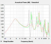
Hornresp already allow to use stub to damp port resonnance. Green without stub, grey stub without damping material, red stub with damping. It totally works experimentally.
The only difference between this sim, and what i try to achieve, is the use of another stub, larger but longer, to be tuned at same frequency, and connect first to second stub end, maybe at a common chamber full of damping material, don't know yet. It's a re-entrant stub. Nothing that much fancy compared to tapped horns yet well simulated, and all the others re-entrant typologies for wich real life result have confirmed.
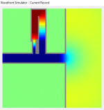
I don't master at all hornesp wavefront sim. But picture 2 gives a idea of the re-entrant tube at port and the nulling effect where red pressure is nulled (somewhat) by blue pressure from first small tube. Very bad sim, but it's the idea. Tuning it, trying, playing around volumes, to see how it turns on port response : i imagine that it's not a simple notch filter contrary to stubs.
The only difference between this sim, and what i try to achieve, is the use of another stub, larger but longer, to be tuned at same frequency, and connect first to second stub end, maybe at a common chamber full of damping material, don't know yet. It's a re-entrant stub. Nothing that much fancy compared to tapped horns yet well simulated, and all the others re-entrant typologies for wich real life result have confirmed.
I don't master at all hornesp wavefront sim. But picture 2 gives a idea of the re-entrant tube at port and the nulling effect where red pressure is nulled (somewhat) by blue pressure from first small tube. Very bad sim, but it's the idea. Tuning it, trying, playing around volumes, to see how it turns on port response : i imagine that it's not a simple notch filter contrary to stubs.
Attachments
Last edited:
I just connected some sleeping neurones...Yamaha did it for back chamber resonnance:

"Mounted on the back of the tweeter and midrange speaker units are newly developed R.S. Chambers (patent pending) that suppress unnecessary tube resonance generated behind the diaphragm. Two specially shaped tubes installed in accordance with our proprietary acoustic analysis cancel tube resonance. These R.S. Chambers achieve higher-resolution audio reproduction by eliminating the need for a large quantity of sound-absorbing material inside the enclosure that tends to smooth the frequency response of each speaker unit and might degrade minute nuances of the sound."
Looking at geometry, there must be 2 resonnances to kill for the midrange, nice !
Last edited:
- Status
- This old topic is closed. If you want to reopen this topic, contact a moderator using the "Report Post" button.