Pafi
Flux is induced in space by magnetomotive force. The space in which the flux is induced constitutes a magnetic circuit. The total flux is dependant on the reluctance of the circuit, and the space, in the case of an air cored copper coil, although stretching out to the ends of the universe, is largely occupied by air and copper. The flux at any point on the 'lines of force' (equipotentials by definition) is the same i.e. it 'penetrates' equally into air and copper just as the current in a circuit is the same everywhere regardless whether the circuit at that point is composed of copper, carbon or silicon (or even air).
'Eddy currents' are those currents which do not contribute to or oppose the main flow (like a whirlpool in a stream). Eddies occur at discontinuities. The gap in a gapped inductor is a major discontinuity. The 'legs' of an air cored inductor represent a minor discontinuity because they are (generally) normal (kind of at right angles) to the other wires in the coil. Because the flux from these 'legs' does not line up with (is not in the same direction as) the flux from the coiled wire it creates (local) currents in the coil which which do not contribute to the main flow of current because they are not in the correct direction.
There is every reason to calculate loss values.
Logic suggests that before looking for complex explanations one should look for simple ones.
I have suggested a simple explanation for what is going on. Until your *calculations* show that the temperature rise is not due to the simple explanation I have suggested, I see no reason to look for a more complex one.
I appreciate that English is not your first language. The word 'penetrates' suggests that the flux pushes deeper into the material the more of it there is. This is simply not the case. Unfortunately in electronics only the exact words will do.
I'm not saying that it is impossible that there is an effect here, all I'm saying is, before we go running off looking for the litz wire, let's be sure that we need it. It wouldn't be the first carburettor I saw replaced when what was actually needed was a new fuel filter.
On another related but slightly different subject, do any of these inductor types have an influence on the sound? I mean-air core vs. ferrite. People looking to use a wide variety of capacitors many of which are rated as sounding better than others. I don't really have the resources for comparative tests, so I generally go by somebody's recommendation.
Flux is induced in space by magnetomotive force. The space in which the flux is induced constitutes a magnetic circuit. The total flux is dependant on the reluctance of the circuit, and the space, in the case of an air cored copper coil, although stretching out to the ends of the universe, is largely occupied by air and copper. The flux at any point on the 'lines of force' (equipotentials by definition) is the same i.e. it 'penetrates' equally into air and copper just as the current in a circuit is the same everywhere regardless whether the circuit at that point is composed of copper, carbon or silicon (or even air).
'Eddy currents' are those currents which do not contribute to or oppose the main flow (like a whirlpool in a stream). Eddies occur at discontinuities. The gap in a gapped inductor is a major discontinuity. The 'legs' of an air cored inductor represent a minor discontinuity because they are (generally) normal (kind of at right angles) to the other wires in the coil. Because the flux from these 'legs' does not line up with (is not in the same direction as) the flux from the coiled wire it creates (local) currents in the coil which which do not contribute to the main flow of current because they are not in the correct direction.
there is no need to precisely calculate exact loss values
There is every reason to calculate loss values.
Logic suggests that before looking for complex explanations one should look for simple ones.
I have suggested a simple explanation for what is going on. Until your *calculations* show that the temperature rise is not due to the simple explanation I have suggested, I see no reason to look for a more complex one.
I appreciate that English is not your first language. The word 'penetrates' suggests that the flux pushes deeper into the material the more of it there is. This is simply not the case. Unfortunately in electronics only the exact words will do.
I'm not saying that it is impossible that there is an effect here, all I'm saying is, before we go running off looking for the litz wire, let's be sure that we need it. It wouldn't be the first carburettor I saw replaced when what was actually needed was a new fuel filter.
On another related but slightly different subject, do any of these inductor types have an influence on the sound? I mean-air core vs. ferrite. People looking to use a wide variety of capacitors many of which are rated as sounding better than others. I don't really have the resources for comparative tests, so I generally go by somebody's recommendation.
Waki,
I've been wondering the same thing... Treating the inductor purely as energy storage... we would like to get back out what we put in, at least in a linear way, and that says air core. That assumes of course, it is possible to mount said inductor where it is not finding a reluctor and some core loss on its own.
But what is the sense in trying to preseve fidelity at a frequency we don't wish to listen to?
Perhaps an inductor with low losses in the audio range is all that really matters?
")
I've been wondering the same thing... Treating the inductor purely as energy storage... we would like to get back out what we put in, at least in a linear way, and that says air core. That assumes of course, it is possible to mount said inductor where it is not finding a reluctor and some core loss on its own.
But what is the sense in trying to preseve fidelity at a frequency we don't wish to listen to?
Perhaps an inductor with low losses in the audio range is all that really matters?
Wakibaki!
This is not true. Lines of force points to the direction of force. This is orthogonal to the equipotential surfaces.
Actually "flux at a point" is a nonsense too. In a point there can't be flux! Flux needs surface! You can specify only flux density in a point! But flux density in not constant along lines of force either.
Not equally, but this is unimportant in this case.
...There are so many mistakes in your next explanation, that I don't have time to correct them. Make your expressions clear in yourself first!
Tell me, what it is? What makes a difference between 50 mW and 200 mW in this case? None of them is able to heat up the shown coils!
Done. Simple explanation doesn't work.
As you wish! Don't see, if you don't want! I have no time to waste.
Sorry, I don't know what "the more of it there is" means.
It's interesting to read this from you.
We don't neccessarily need it. This is only one of the many solutions, but it works.
The flux at any point on the 'lines of force' (equipotentials by definition) is the same
This is not true. Lines of force points to the direction of force. This is orthogonal to the equipotential surfaces.
Actually "flux at a point" is a nonsense too. In a point there can't be flux! Flux needs surface! You can specify only flux density in a point! But flux density in not constant along lines of force either.
it 'penetrates' equally into air and copper just
Not equally, but this is unimportant in this case.
...There are so many mistakes in your next explanation, that I don't have time to correct them. Make your expressions clear in yourself first!
There is every reason to calculate loss values.
Tell me, what it is? What makes a difference between 50 mW and 200 mW in this case? None of them is able to heat up the shown coils!
Logic suggests that before looking for complex explanations one should look for simple ones.
Done. Simple explanation doesn't work.
Until your *calculations* show that the temperature rise is not due to the simple explanation I have suggested, I see no reason to look for a more complex one.
As you wish! Don't see, if you don't want! I have no time to waste.
I appreciate that English is not your first language. The word 'penetrates' suggests that the flux pushes deeper into the material the more of it there is. This is simply not the case.
Sorry, I don't know what "the more of it there is" means.
Unfortunately in electronics only the exact words will do.
It's interesting to read this from you.
I'm not saying that it is impossible that there is an effect here, all I'm saying is, before we go running off looking for the litz wire, let's be sure that we need it
We don't neccessarily need it. This is only one of the many solutions, but it works.
jneutron said:
Cube?
Ahh, I see the difference.. In my work, we consider the field falloff radial to the dipole. It is 1/R, with uniform field inside. For quads, it is 1/R squared, with 1/R in the middle. For sextupoles, it is 1/R cubed, with internal field 1/R squared.
You are speaking of a solenoid..
1/R? What structure did you calculate? It musn't be a finite coil in 3 dimension, because it have an infinite energy!
A monopole have an 1/R^2 field (at least in 3D). A dipole must fall faster! A dipole can be assumpted by 2 monopoles (+ and -). If monopoles are in (0,0,1) and (0,0,-1), then direction of force in (R,0,0) is (0,0,1), and magnitude is H=2/(1+R^2)*1/sqrt(1+R^2). If R>>1, then this is appoximately: H=2/R^3.
You can calculate it relative easily on a single turn wire frame too, but please let me not to do it!
Alas, it is but a simple confusion of terms.
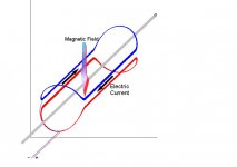
To me, a dipole is a bending magnet for a particle beam. Not to be confused with a dipole such as is created by a solenoid.
http://en.wikipedia.org/wiki/Dipole_magnet
While this depicts a room temp magnet, I work with magnets where the current density of the cylinder is of the cosine (N*theta) variety...for dipole, n=1, quad n=2, etc.. This is of most use with superconductors.
While the topology of an accelerator dipole is that of a solenoid, we worry about the field off to the side of the dipole.
Heres a depiction of a simple dipole..the grey line is the direction of the particle beam. Within the structure, the field is uniform, outside it falls off as 1/R.
As you note, if it truly fell off as 1/R for infinity, there would be infinite energy. The 1/R relation is good for R <Length of magnet.
Cheers, John
Attachments
Thank you for the explanation! I ment dipole in general meaning.
Indeed, your coil have 1/R field, if length>>R>>diameter.
And I realized that although a solenoid have 1/R^3 field in radial, but 1/R^2 in axial direction, so 1/R^2 is valid here. Your advice of rotating the coil 90 degrees off is a good idea.
Indeed, your coil have 1/R field, if length>>R>>diameter.
And I realized that although a solenoid have 1/R^3 field in radial, but 1/R^2 in axial direction, so 1/R^2 is valid here. Your advice of rotating the coil 90 degrees off is a good idea.
- Status
- This old topic is closed. If you want to reopen this topic, contact a moderator using the "Report Post" button.
- Home
- Amplifiers
- Class D
- Air Core inductor: Hole Size ! (waveforms shown)