Fractures were at the lower end of driver openings, not at bolt holes. If there was room for ellipsoid driver holes, plate would be more resistant to fractures (distribution of bending forces)
Birch plywood like the original (aircraft grade, thin films) would be nice and tough yes... I guess that the 2,5kHz peak at 90¤ comes from the straight edges of Neo8 hole. Chamfering would help but it makes structure even weaker. Neo8's stamped-plate frame is too ugly to be mounted to the frontside of the frame! I have been thinking of mounting the NeoCD to the backside too.
Tweeter will be too low if I mount it next to 12" and it has very narrow vertical beam.
Last edited:
Eldam, from Rudolf Finke's web page you can download "white papers" about using dipoles and setting crossovers wisely. The German version is much wider, so you can download it or bot German and English versions.
Siegfried Linkwitz and John Kreskowsky also have lots of valuable info on their pages.
The comfort zone of a dipole driver reaches to somewhere between dipole peak and null. Directivity and response behave very constantly up to there. At and above the dipole peak directivity gets irregular and summation suffers. The frequency of dipole peak and null are determined mainly by baffle dimensions (minimum diameter), - corresponding to wavelength/2. Edge By Tolvan is an easy and reliable simulation to see baffle effects.
Graphics from SL web page
Last edited:
Fractures were at the lower end of driver openings, not at bolt holes. If there was room for ellipsoid driver holes, plate would be more resistant to fractures (distribution of bending forces)
Birch plywood like the original (aircraft grade, thin films) would be nice and tough yes... I guess that the 2,5kHz peak at 90¤ comes from the straight edges of Neo8 hole. Chamfering would help but it makes structure even weaker. Neo8's stamped-plate frame is too ugly to be mounted to the frontside of the frame! I have been thinking of mounting the NeoCD to the backside too.
Tweeter will be too low if I mount it next to 12" and it has very narrow vertical beam.
We would scrape the rough edges and buff them out with various rouges (experimental aircraft canopies). Can see the mass that thin plastic must support bein a tad wibbly. A couple of carbon rods epoxied in would fix that strength issue.
Dug out a wheelchair tray (never used made wrong) from my storage that's 8mm thick which would work perfect. In my case tho it'll mostly be used for various router bases.
As for flipping the panel, I can see possible issue of doing such due to the length of the Neo8. Tweeter height would remain the same... may require raising the LM position. Modeled the MT arrangement for mine (as opposed to standard MTM), which actually may become an MMT with the upper M 60° off axis facing up and the lower MT is on axis. This improved the tweeter lobing issue all TM arrangements have. As only a suggestion to try (or model in EDGE) and see. Your horn may have a significant difference compared to my AMT's so this may be a non issue for you. Just thththinking
")
Should finish my circle jig today and the portable router table I made up out of two (crap) speaker boxes a neighbor tossed. When I started this project a year ago never put much thought into the actual cutting of material for these projects. I'm in an apt and had a guy for that. He's unable now (medical reasons), which is a shame, great guy, semi retired ex owner of a cabinet company with an eye like a laser.
Cheers
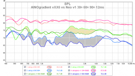
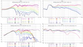
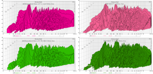
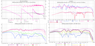
Overlay of AINOgradient Neovs. vXX6
I have poured paint in areas where Neo8 outperforms the Vifa NE95 cone mid drivers, in regard of dipole function. Crossovers for these drivers are
Neo8-PDR 800Hz LR4 and 4000Hz LR8
NE95W 800Hz LR4 and 3000Hz LR4
A narrow planar driver gives much smoother response above 1,5kHz, because it maintains pure dipole response much higher. This is a magnificient result!
On-axis (not shown here) and 30¤ are practically same, but here Neo8 verison does not have the 6.9uF serial capasitor. With that added (or eq) the boosted range around 3,5 - 5kHz woud be similar, and the benefit for Neo8 would reach even higher in F.
The xo between Neo8 and NeoCD3.5H will be reconsidered after making also vertical off-asi and room response measurements, and of course listening tests. These will be done after Christmas, when I get new stronger frames!
Attachments
"Fractures were at the lower end of driver openings, not at bolt holes."
Are you referring to the corners of the opening? If so, consider a radius here instead of a square cut out. In plastics, a sharp (even "not so sharp") 90* cutout corner will develop cracks because of the stress imposed by the cut. A radius eases spreads the stress in the material at these points. Just a simple 1/8" radius will do the trick.
Are you referring to the corners of the opening? If so, consider a radius here instead of a square cut out. In plastics, a sharp (even "not so sharp") 90* cutout corner will develop cracks because of the stress imposed by the cut. A radius eases spreads the stress in the material at these points. Just a simple 1/8" radius will do the trick.
Last edited:
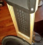
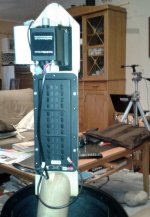
I invested 5€ for a piece of 9mm thick Finnish birch plywood, std quality and made new frames. I wanted to keep width at minimum 90mm, but despite of chamfered edges the Neo8 has some cavity interferences because of it. I can make alternative baffles that are a little wider but with recess for the driver. I don't like how they look, I must try to figure out something new...
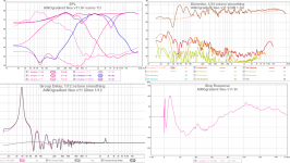
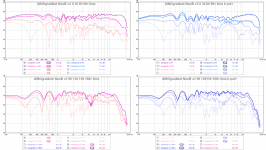
Indoor measurements show well behaved directivity especially the problematic 2-4kHz range. Vertical off-axis is acceptable, 0-level is at the lower edge of tweeter. Distortion is much better than previously between 600-2kHz.
Listened only briefly so far, but it seems like there is added definition and clarity in eg. piano right hand and cymbals. I am wondering where that comes -lower distortion, better dispersion or backwaves reaching higher. Perhaps it is the driver, faster decay? Anyway - success! I think this version will serve me for Christmas holidays
Drivers and xo AINOgradient Neo v11
W SEAS L26ROY4 sealed 130Hz LR2
LM Beyma 12MWNd dipole 800Hz LR4
HM B&G Neo8öPDR dipole 4000Hz LR4
T Fountek NeoCD3.5H
Attachments
-
 AINOgradient Neo close.jpg158.1 KB · Views: 259
 -
 AINOgradient Neo back.jpg119.3 KB · Views: 357
 -
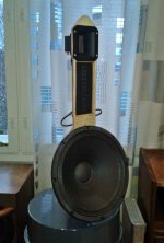 AINOgradien Neo pole.jpg105.9 KB · Views: 524
 -
 ainogneo v11 off-axis.png523.8 KB · Views: 520
 -
 ainogneo v11 0¤ all indiv disto gd step.png465.5 KB · Views: 525
 -
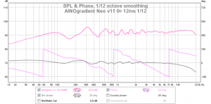 ainogneo v11 0¤ spl phase 12ms 112.png58.1 KB · Views: 198
 -
 ainogneo v11 0¤ room lr 300ms 16.png71.2 KB · Views: 132
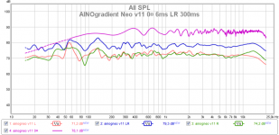
In those room response measurements distance was 70cm. ~40¤ to the wall. For serius listening I pull them to 90-100cm off the front wall, easy and it just makes them to be virtually wider for stereo image. My side walls are 2m away, speakers are on the long wall of the room.
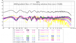
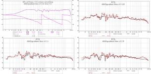
"Listening window" overlay here.
I used horizontals 0-30¤ and vertical on-axis -10 - +15¤ with 5¤ steps - not by book but close enough. We see how hor and vert directivity work together.
Good enough! Low treble range is perhaps too hot, it depends on personal taste. The response can easily be tweaked by personal preference, either for each driver or global eq. Global (input) eq with minidsp is perhaps best from now on, the basic performance is just fine.
Attachments
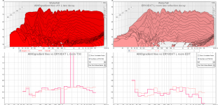
CSD and EDT from room response measurements, distance 210cm, speakers 70cm to front wall. Also compared to ER18DXT (mod) which are normal boxed 2-ways, at same position/setup.
The greatest difference is in tweeter range, the horn ribbon has very fast decay with minimal room reflections. Despite of dipole backwaves, mid region has faster early decay than monopole, but difference is small. Late reflections are stronger with dipoles.
Decay spectrograms of AINOs only. For some reason REW refuses to generate them from ER measurements.
Attachments
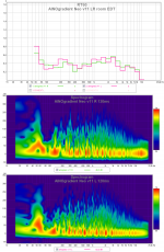
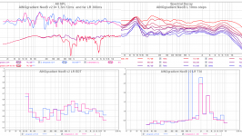
I did some fine tuning and voicing based on listening and RTA measurements. RTA with infinite averaging and moving the mic around my head during the measurement, pulsating pink noise.
Room does not have any acoustic treatment. Room modes and reflections make wiggles, basic shape of the graph comes from the speakers total 3D power response.
1,5 -2,2kHz might still be too hot, but this sound clear and defined, not at all hard or sizzling.
Now just even more listening of various music during holidays...
First measurement is on-axis at 1,2m with the speaker in the middle of the room. RTAs with speakers on normal position and mic hoovering around my head at listening chair.
Attachments

Really appreciate the fact you have little room treatment. The balance is excellent considering and that brightness in the mid is a non issue being active, pinna dictates that for us all differently anywho
There is an optical trick that can be done when looking at your graphs side by side (as above) where you cross your eyes and overlay the graphs upon each other. If either the left or right rta's were to have one of the two red lines changed to green the difference and equality can be keenly seen.
---
Update; test MLTL is almost done. Single 6.5" driver for this box (tube) standing (w/~2.5" lift off floor) is about 49" (~124.5cm) for a line length of ~76" (1.93m). As this is an experiment the finished product would be at least another 1.5" taller min. Each of the two towers will have 2 of these combined with two more 6.5's sealed Q 0.62 to cover the bass requirements.
Yeah it's rather big. Something like ~51" (130cm) tall, 23" (58.4cm) wide and not deeper than 24cm, a tad over 9". Front baffle is still 7" (may add upto 2cm to this)
After fridays goofup, my toroids should be here today.
Wife is experiencing an epiphany now that I have some woodworking tools. Lots of little projects for me to do now Go figure
Merry Christmas Juha, Aino & family
Mike
Really appreciate the fact you have little room treatment. The balance is excellent considering and that brightness in the mid is a non issue being active, pinna dictates that for us all differently anywho
There is an optical trick that can be done when looking at your graphs side by side (as above) where you cross your eyes and overlay the graphs upon each other. If either the left or right rta's were to have one of the two red lines changed to green the difference and equality can be keenly seen.
---
Update; test MLTL is almost done. Single 6.5" driver for this box (tube) standing (w/~2.5" lift off floor) is about 49" (~124.5cm) for a line length of ~76" (1.93m). As this is an experiment the finished product would be at least another 1.5" taller min. Each of the two towers will have 2 of these combined with two more 6.5's sealed Q 0.62 to cover the bass requirements.
Yeah it's rather big. Something like ~51" (130cm) tall, 23" (58.4cm) wide and not deeper than 24cm, a tad over 9". Front baffle is still 7" (may add upto 2cm to this)
After fridays goofup, my toroids should be here today.
Wife is experiencing an epiphany now that I have some woodworking tools. Lots of little projects for me to do now Go figure
Merry Christmas Juha, Aino & family
Mike
---
Update; Toroids arrived (happy dance), now for the joy of rewinding them (similar to rebuilding an engine, just a hassle
Now for filter caps, what say 50,000uF per rail should be sufficient to start. Over to fleabay I go for 200,000... One question that I need to look into is if I should install a softstart/current limit the inrush. 625VA is stepping into that territory. Can possibly see two of these popping a breaker if energized at the same time on the same circuit. Hmmm
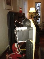
Joulupukki (Santa Claus, Julgubbe, der Weichnachtsmann) visited us and obviously i have been nice too, because I was given a pair of Peerless Definition 1" automotive tweeters!
I got a little help from the elves and installed one today. I don't have any minidsp channels free, so I can only try parallel vs- serial and polarity change effects.
I decided to try backfire tweeters because decay plots and room RTA measurements show that decay above 3kHz is very rapid. It comes because of lack of rearwards radiation and late reflections. My xo is now around 4kHz LR4 or LR8. I'll do and show measurements when I have time and don't disturb the family!
Attachments

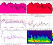
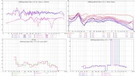
Some measurements of AINOgradient NeoB with back-firing tweeter
A dipole and omnipole radiate equally to 0 and 180¤ but monopole does not. AINO have monopole tweeters but now I tested bacfiring tweeters, connected parallel to NeoCDs. Rear tweeters are pointing 45¤ up because I don't want maximal power to push straight backwards.
This gets a little difficult, we are mainly looking at time domain changes here. Frontside on-axis is not affected at all in short gated measurements, differences appear off-axis and with longer IR gate (time domain).
The problem is that I don't have a minidsp channel left, so I can not use delay, eq etc. adjustments. The acoustic center of the reat tweeter is about half wave length bac, this results in strange summing behaviour that we see mainly in backside measurements. The last compilation shows the difference of changin polarity of the backfire tweeter.
After the nearfield directivity measurements I added 1x2cm pieces of felt on top of rear tweeter grilles, to attenueate them a little. Measurements with L or LR showin in the topic are fardield 2,2m with speakers on normal listening positions.
Measurements show different amplitude response off-axis from 75¤ to 180¤ - making power response different and boosting decay'd response above 3kHz.
A friend will visit me tomorrow, we will try to hear these changes! I must say that I'm not sure if I hear any difference with my impaired ears.
Attachments
Last edited:
- Home
- Loudspeakers
- Multi-Way
- Aino gradient - a collaborative speaker project