leadbelly said:Sorry if some feel this is threadjacking, but are you guys serious about these "noise cancels in theory" comments? I'm not an EE, but from what I know, this sounds like hogwash. I would think that even a simple tube circuit is not purely deterministic and so neither noise nor any other signal component could not be manipulated in such a manner. Feel free to call me stupid if this is just over my head.
It seems to work well enough in 3G mobile phones.
hi bas, thanks for reply! to be somewhat clearer on the ac filaments..i'm using the 6v supply off tranny and have the fil in parallel. sucks more current but oh well! the filaments on tranny is center tapped and refenced to ground, so would this be equivalent to what you suggested? to create a tap to earth. directly off tube fil. tap? can you use your method with either series or parallel connection-series the filament tap on tube is not connected, i thought about 12v series and have a tranny but the other way was faster and i saw no advantage..i'm probably wrong...
and yeah, there is very little ps hum, and i'm sure i can fix that. it's mostly that high frequency tube "hash" except it's border line objectionable. i run 99db horns..you get the picture..ha!
thanks much for help, i think i'll try the ref to a voltage, this weekend coming up. i may also try dc fil. as i have a little bridge with filter caps made and gathering dust.. both tubes (12au7-12bh7) have a 200 volt cathode/fil rating and i'm not past that, so i'm safe for now.
take it easy-charlie
In the Aikido circuit there is a gain stage loaded by an identical tube so that half the supply voltage appears at its anode. This drives the grid of a cathode follower that is also loaded by a tube at its cathode.
The first stage splits the supply in half (assuming you have 2 identical triodes) therefore the noise on the HT line is halved with it and will appears on the grid of the CF stage.
The cathode followers loads' grid is connected to the supply by a divider with a series cap blocking the DC components but providing the grid with 1/2 the supply noise also.
This noise causes the cathode followers load to swing in phase with the cathode followers cathode with the supply noise and theoretically cancels it all out if the tubes used in each stage are identical.
I hope i explained that ok, probably a bit confusing with the wording.
Craig
To HiFiNutNut
Yes Bill I did try all variations of PSU on the Aikido breadboard .
The better the supply the better the sound. Not a small difference either.Multiple chokes and poly caps sounded way better than a simple supply. I have a multi tap mains trans so it makes things easy to change.
Yes Bill I did try all variations of PSU on the Aikido breadboard .
The better the supply the better the sound. Not a small difference either.Multiple chokes and poly caps sounded way better than a simple supply. I have a multi tap mains trans so it makes things easy to change.
It might be worth pointing out again the importance of getting the
noise reduction voltage divider resistors just right for your choice
of valves in order to maximise PSRR. I refer to this blog:
http://www.tubecad.com/2005/July/blog0051.htm
The simple way is to make one of the resistors variable, so that
you can tune away the noise (using headphones or sensitive
speakers, for example).
I didn't use a variable resistor, just calculated the right values for
the valve I used for the 2nd stage (6N30P). My Aikido is DEAD
quiet! First, I thought it was dead - period! But beautiful sound
came out of it. (Input stage is - hold your hat... - 7E6.)
I used different heater winding for upper and lower valves, in
both cases sitting ca 35V above the respective cathodes. Both
divider points bypassed with 2uF. And, of course, balancing resistors
across the heater feeds. Heater is AC - no problem! PSU has hybrid
bridge (7Y4/BYV26E), 33uF cap, 15H choke, 300uF (100 common
plus 100 per ch.). Not saying a better PSU would hurt, though.
That's all. Also use it as a headphone amp (I run the CF at 25mA) -
NO perceptible noise.
Morgan
Morgan, that is a good result no audible noise.
Have you checked it on a scope to see exactly what is there?
I intend to attach a 5K trimmer to the lower 100K resistor as soon as i get some decent tubes to work with.
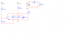
here is a quick idea for a p-channel JFET muter for people who want to use tube regulated supplies like me.
I dont know if it works yet as my sim doesnt like it.
It should also mute the output on turnoff too but it depends on how much capacitance you have in your supply.
The 100 ohm resistor represents the output impedance of the aikido (just a guess) and the 33K is the input impedance of the power amp.
will it work do you think?
Craig
Have you checked it on a scope to see exactly what is there?
I intend to attach a 5K trimmer to the lower 100K resistor as soon as i get some decent tubes to work with.
here is a quick idea for a p-channel JFET muter for people who want to use tube regulated supplies like me.
I dont know if it works yet as my sim doesnt like it.
It should also mute the output on turnoff too but it depends on how much capacitance you have in your supply.
The 100 ohm resistor represents the output impedance of the aikido (just a guess) and the 33K is the input impedance of the power amp.
will it work do you think?
Craig
Attachments
I haven't checked it on a scope (mine is broken ). But I
can't hear the faintest noise through sensitive headphones (HD580)
so there probably isn't much to see. Maybe I was lucky with the
choice of valves also?
Will the muter work? Don't know, looks strange to me - like it would
turn on when it should turn off, possibly. Are those P-channel FETs?
No - I don't get it. Sorry.
I always use this (near bottom of page - NB slow loading page):
http://www.klausmobile.narod.ru/appnotes/an_13_tl_e.htm
That's a double one - just remove one of the TL431s and associated
cap and resistor. Works a treat. But needs a relay, which is normally
closed, and shorts the output to ground. So when you turn on,
after a delay the relay is activated and opens the output. Runs off
the heater PSU (AC) via a voltage doubler with small ripple caps.
That way, it turns off very quickly when you turn off the amp. This
is paramount for an output mute circuit. If you run it off B+, it won't
turn off until it's effectively too late to prevent a transient.
Morgan
). But Ican't hear the faintest noise through sensitive headphones (HD580)
so there probably isn't much to see. Maybe I was lucky with the
choice of valves also?
Will the muter work? Don't know, looks strange to me - like it would
turn on when it should turn off, possibly. Are those P-channel FETs?
No - I don't get it. Sorry.
I always use this (near bottom of page - NB slow loading page):
http://www.klausmobile.narod.ru/appnotes/an_13_tl_e.htm
That's a double one - just remove one of the TL431s and associated
cap and resistor. Works a treat. But needs a relay, which is normally
closed, and shorts the output to ground. So when you turn on,
after a delay the relay is activated and opens the output. Runs off
the heater PSU (AC) via a voltage doubler with small ripple caps.
That way, it turns off very quickly when you turn off the amp. This
is paramount for an output mute circuit. If you run it off B+, it won't
turn off until it's effectively too late to prevent a transient.
Morgan
They are P channel jfets so they are in full conduction when there is 0 V between gate and source, so charging up a cap at Q1's gate will bring it out of cunduction. Therefore at start up the output is shorted until the cap charges to about 5.6V then the FET should be off completely allowing the music though.
Discharging the cap via the other p-channel fet (Q2) (assuming its gate can be brought ot 0 V before the thump) will bring Q1 back into conduction shorting the output again at turnoff.
As you said at the end of your post the tricky part is getting the voltage to the mute circuit low enough before the transient at the output caused by the regulators dropping out
I dont really have room to use relays unfortunatly.
Craig
This weekend I have built an Aikido . It is done all P2P, it is so simple I cannot see the advantage of a PCB. I used an ECC40 for both positions, and I have to say it works very well.
Before I used a 6072 pre that was really nice but this Aikido is seriously better.
The ECC40 needs a rimlock socket which makes it difficult to try other valve types, but maybe I will build a second one with noval or even octal sockets someday.
Anyway, very much recommended!
Before I used a 6072 pre that was really nice but this Aikido is seriously better.
The ECC40 needs a rimlock socket which makes it difficult to try other valve types, but maybe I will build a second one with noval or even octal sockets someday.
Anyway, very much recommended!
Hi Peter, we can't all be as good as you.It is done all P2P, it is so simple I cannot see the advantage of a PCB.
")
I have to admit, I made a mistake with my first P2P...did not find it all that easy. Now imagine if you have never built a valve/tube amp thingy before..the Aikido can be positively daunting.
Sure, it happens but I make mistakes with PCB's as well, things like putting electrolytics the wrong way roundI have to admit, I made a mistake with my first P2P...

Btw Bas, I noticed on your site you built a Cleo5 preamp, have you been able to compare that to your Aikido?
I did compare it quickly... I preferred the Cleo..there is this something with DHT's I like..the way the soundstage is so big.
But then again the Cleo had BG's and amorphous chokes in the psu...the Aikido had a psu I quickly threw together..with back to back little surplus transformers etc..etc..
That Cleo I built probably cost a 100 times more than the Aikido I built first...seriously
So it was like comparing apples with pears. One should really use the same psu and volume control etc...to do a fair comparison.
Audio Output Buffer
Hello, I'm looking for a circuit diagram for Audio Output Buffer which similar with Musical Fidelity X10v3 (http://www.musicalfidelity.com/mf/en/Products/SmallX), Thanks
Hello, I'm looking for a circuit diagram for Audio Output Buffer which similar with Musical Fidelity X10v3 (http://www.musicalfidelity.com/mf/en/Products/SmallX), Thanks
Been lurking at this Aikido pre for awhile and am starting to think about what tubes to use. My question is what combination of tubes do you like and which ones didn't work?
I'll need some gain but not too much. Also I'm looking for resolution and depth. Will have to buy these tubes so would like to get a proven combination. TIA...
I'll need some gain but not too much. Also I'm looking for resolution and depth. Will have to buy these tubes so would like to get a proven combination. TIA...
Hey Jan,
Should do fine. The output of the Aikido is a cathode follower. Cathode followers have low output impedance and will definately be able to drive the 17k input impedance of your power amplifier.
[edit] Plus the Aikido apparently behaves very well with difficult loads.
Regards,
Bas
Should do fine. The output of the Aikido is a cathode follower. Cathode followers have low output impedance and will definately be able to drive the 17k input impedance of your power amplifier.
[edit] Plus the Aikido apparently behaves very well with difficult loads.
Regards,
Bas
- Status
- This old topic is closed. If you want to reopen this topic, contact a moderator using the "Report Post" button.
- Home
- Amplifiers
- Tubes / Valves
- Aikido line stage results? share yours