Hello,
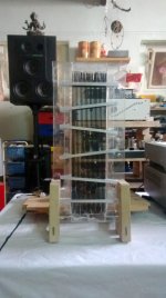
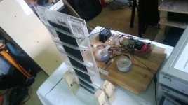
my name is Christoph and I will build an ESL right now after thinking about it the last 10 years. I want to build a wire stator (1,1 mm diameter wire), about 3 inch wide and 31 inch high. It will be a hybrid. I have no questions so far, but I have been reading this forum for days and weeks and I would like to thank you all for your input, it is the best forum for ESL-DIY I know. The only thing I can give back are some pix....
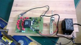
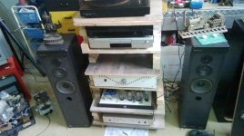
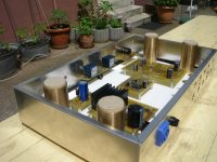
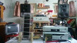
The pictures just show some of the material I have gathered so far. The last pix show my "equipment", nothinmg special, just a SE amp with EL34 and a simple Gainclone. I love both, never owned a comercial amp until now, and I am 37 years...... Sorry for my bad English, school is far away")
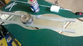
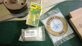
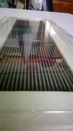
Starting with the Stator, the Pix show some small parts, elvamide and mylar that I bought from the audicircuit (Hans Zeuwe) 10 years before, my homebrew "rack" and my preamp, work in progress.
Thanks to Jazzman, Calvin and all the others!!!! If the ESL will play, good! If not, I will start all over again, its a hobby in the end.....
Christoph
my name is Christoph and I will build an ESL right now after thinking about it the last 10 years. I want to build a wire stator (1,1 mm diameter wire), about 3 inch wide and 31 inch high. It will be a hybrid. I have no questions so far, but I have been reading this forum for days and weeks and I would like to thank you all for your input, it is the best forum for ESL-DIY I know. The only thing I can give back are some pix....
The pictures just show some of the material I have gathered so far. The last pix show my "equipment", nothinmg special, just a SE amp with EL34 and a simple Gainclone. I love both, never owned a comercial amp until now, and I am 37 years...... Sorry for my bad English, school is far away
Starting with the Stator, the Pix show some small parts, elvamide and mylar that I bought from the audicircuit (Hans Zeuwe) 10 years before, my homebrew "rack" and my preamp, work in progress.
Thanks to Jazzman, Calvin and all the others!!!! If the ESL will play, good! If not, I will start all over again, its a hobby in the end.....
Christoph
Attachments
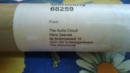
My "first contact" was the "Audio Circuit", at that moment I started collecting all the information I could find about ESLs. I will keep you informed about my progress, but my problem is huge, too many interests, too little time .
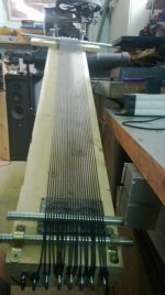
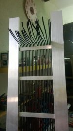
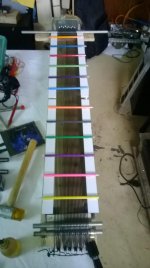
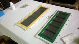
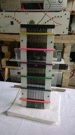
In the moment I am building a simple stretching frame for the Mylar and a even simpler stretching frame for the wires...
Greetz
Christoph
.In the moment I am building a simple stretching frame for the Mylar and a even simpler stretching frame for the wires...
Greetz
Christoph
... it's not my fault, it was broken already..
.... it was my evil alter ego calvin-boy nr.5 who made them do it
Itwasthealien
.... it was my evil alter ego calvin-boy nr.5 who made them do it
Itwasthealien
Last edited:
The frame is best made out of a highly insulative material.
There was a thread discussing the issues of the effects of using conductive support bars for the wires and how they can/will cause issues with the electrical segmentation,~I.E. capacitively coupled AC Shunts if you will between each (and all) of the sections.
jer
P.S I would definitely consider coating the frames with about at least 10 mil of some clear laquer of some sort.
Clear Acrylic Enamel is my choice and I have found it to work very well, with as much as 1500v to 2100v per mil of dielectric strength.
Last edited:
Laminating some thick plexiglass or acrylic sheet between the wires and supports will help a great deal with the shunting effect.
.090" to .125" thickness (3-4mm) should be alright.
Coating the frames is more of a safety factor than anything else.
Even though you may end up only running less than say 3kv of bias, the voltage that is coming out of the step-up transformers is much much higher, typically 10Kv to 20Kv p-p across the stators when pushed from moderate to high levels.
Depending on your amplifier capablity and transformer step up ratio.
My Crown DC300a will produce 150-200watts and this comes to about 4.5kv peak just out of one Antek 1206 transformer.
You will need two transformers so already we are at ,at least 9Kv p-p!!!
jer
Last edited:
Done!
It is alive!!!!!!! No stereo, just one channel, still waiting for the second pair of transformers.
It is loud! No crossover, but there is bass!
Feels like christmas and birthday together!
Chris
It is alive!!!!!!! No stereo, just one channel, still waiting for the second pair of transformers.
It is loud! No crossover, but there is bass!
Feels like christmas and birthday together!
Chris
Attachments
Hi tyu,
I use two trannies, 50VA, 230 primary and 2 x 6V secondary, just like Charlie describes it
Jazzman's DIY Electrostatic Loudspeaker Page: The Electronics Package
The cheapest source for me was this company in Germany:
IT-Tronics - Ringkerntrafo Sedlbauer: 50VA 230V -> 2x6V / 1x12V ; 2x4,17A / 1x8,34A
Greetz,
Christoph

Thanks, I am at the beginning now, there is a lot to learn.....
In the moment I am building 4 Panels, 10 cm x 80 cm, 1,5 mm Spacing, same hardware. I am stuck to this dimension, because the stretching frame und the wire stretcher is limited in size.
In the end I will have 4 ESLs, 2 per channel, what could I do:
1) two panels one at the top of the other (160cm x 10 cm)
2) Two panels next to each other (20 cm x 80 cm)
3) stacked Panels
Could anybody kindly explain me the consequences?? I know, all the information is available here, but for me it is hard to put it all together..
(PS: I have one spare panel, the first one I made, it is working (10 cm x 80 cm) but only at low volume. I would give it away for free, except shipping cost, Please PM)
1) Louder.
2) Louder, more bass but more directional.
3) Stacked has little benefit I know of.
You could arrange them next to each other but at an angle, but you might want 3 per channel, making some thing like 80cm X 24cm or the best solution (in my opinion) which is to segment them and run them next to each other.
Hi there!!
I have a thread where I had tried to put some explainations to the type of questions that you have.
I show some simulations as to what happens to the Horizontal and Vertical Dispersion as the diaphragm gets wider and/or the frequency goes up as per width.
Also the possibilities of what happens to the line source wavefront as the panel gets longer and Segmentation vs Non-segemented along its length.
As well as what it takes to help get some lows out of a panel of similar size as yours and what to expect per your dimensions using some online calculators and spreadsheets.
I will be happy to answer any more questions you may have if you have any.
Most everything is explained in the thread.
This is where it starts at the simulations,
A Segmented Stator Desktop ESL
I thought that I had already mentioned this here, But I guess I didn't.
I tried stacking them behind each other but there is no benefit from doing so except for maybe helping to keep the diaphragm under control at very low frequency's and very high excursion rates.
I even tried both configurations of hooking them up in parallel and in series.
Hooking them in series dropped the efficiency as this cut the voltage applied to each set of stator's in half giving each panel less drive.
This may work well for a large Bass array and is something I plan on exploring further sometime.
Martin Logan uses two diaphragms stacked on the bass section of their largest design (CLX I think).
I tried setting the panels side by side and this works as well to increase the efficiency.
But it takes careful adjustment of the panels angles to each other to minimize the lobes.
Ultimately you never do really get rid of them completely.
I found that they sounded better when they were all flat in comparison to each other just the same as a wide panel that has been mechanically segmented such as in Charlie's design.
It is something to experiment with though.
I also found that I had to feed the bias to each panel separately through its own resistor to run them in parallel.
Because of the different and inconsistent resistances of the stator coatings in each individual panel I got a strange effect of voltage hogging between the panels.
As I varied the Bias voltage the sound would literally move left to right and back between the three panels.
With sound only coming out of one end (left) and none coming out of the other ones (right) and then vice versa as the bias was adjusted.
It was Panning just as the Balance knob would do only it was all mono with one amplifier channel driving them!!!
The goal of my design was to run very high voltages in order to push the excursion as far as it will go in order to get good High Performance too as low as 200Hz to 300Hz and lower.
Since my diaphragm resonance was about 70Hz to 90Hz it wasn't a very good thing once I dropped down into this range and the Diaphragm clipped (slapped) into the stator very easily as expected.
I did this with my First little panel and I was able to detect with a Microphone, Diaphragm to Stator clipping and it was quite very loud even down to 200hz with a D/S of about .072" (1.85mm).
I did this with extremely high voltages of about 20Kv to 25Kv p-p on the stators and about 6.5Kv and higher of bias voltage.
I used about 1:256 of transformation ratio and my Crown DC300A at full tilt with about 120Vp-p or so in to the step-up transformer.
It lasted for about 15 to 20 minutes under those conditions and ultimately failed and I burned up the panel as it exploded into flames.
I was able to repair it to some extent and continue testing but I never was able to reached those limits again after that.
On my last attempt I burned it past the point of it being usable at all, So I started a new design.
I spent more time and materials trying to repair the damaged panel than what I could have spent just building a new one with the Flaws fixed in order to handle such voltages.
But, I did get a lot of good testing out of it for the newer model.
I will be building a new one of the same design (using Window Screen) as the panel I burned up.
To compare to and see if my improvements of stator coatings actually work for the design.
I know it will work fine for normal listening but I want to see how far I can push it and squeeze every last little drop of efficiency out of them with 10KV of Bias.
I got it there but after it was damaged it proved very difficult to contain that high of voltage.
I don't suggest using those high of voltages at first until you know what you are getting into, But I was able to run 6.8Kv safely and consistently for most all of my tests.
A large panel doesn't require such high voltages to reach such levels of SPL due to the increased surface area.
I didn't have an SPL meter at the time I had revived them, But it was so loud that even I could not barely stand it for very long.
I dare any one to stay in the same room for 5 minutes at such levels with music and certainly not for test tones!!!
I was quite amazed once I had finally got a proper drive system set up for it as the first time I had ran it it was just mediocre and listenable.
I had no Idea that the very same panel could/would ever reach such levels of performance!!!!
Here is a thread in the final days of that panel,
A Desktop ESL Build
I have many posts here as well describing the panels in more detail but they are buried in several threads.
You can find them if you search for them around the beginning of 2010 in starting in February and March.
It was back when I discovered how to use the Toroid Power transfomers to drive them with in this forum and got them running again for the First time in 7 years.
Enjoy !!
jer
Last edited:
Thank you very much for the answers!
In the meantime I have build another panel, just for training
Sound is good, coating works good (thanks Jan), sound is ähm....colorfull
Jer and all the others, indeed I have some more questions
- I will build bigger Panels in the future but I don´t want to waste these small panels, so I need a kind of woofer to mate with them. I have no possibility to measure my panels and most information about woofers and subwoofers in this forum are about much bigger ESLs, so what to try? I would use these speakers just for casual listening... I am looking for a cheap solution, I will spend my money with the upcomming bigger panels
- Second, could electrical segmentation help to "optimize" theses little panels?
Thanks a lot,
Christoph
Attachments
- Status
- This old topic is closed. If you want to reopen this topic, contact a moderator using the "Report Post" button.
- Home
- Loudspeakers
- Planars & Exotics
- After 10 years, starting with my first ESL