I have said before that it's a little confusing, but what I mean is that when
the 2nd harmonic peaks positive with the fundamental peaking positive, I
call that "in phase". When it peaks negative when the fundamental is
peaking positive, that is "out of phase".
The alternative description is that when the 2nd is "in phase" the fundamental
is showing slight expansion in the positive half and slight compression in the
negative half.

So how do you test/visualize (what equipment is nessesary) to tell whether the second hormonic is "in phase" or "out of phase"?
I have said before that it's a little confusing, but what I mean is that when
the 2nd harmonic peaks positive with the fundamental peaking positive, I
call that "in phase". When it peaks negative when the fundamental is
peaking positive, that is "out of phase".
The alternative description is that when the 2nd is "in phase" the fundamental
is showing slight expansion in the positive half and slight compression in the
negative half.
It took a while but my dumb brain understands your description.
It's definitely the best way to describe it.
Initially most of my confusion was with visuallising the harmonic waveform then I had one of those face palm moments, and it all made sense. Haha
The expansion/compression explanation is easiest to understand for a melon head like me, but almost impossible to see on an oscilloscope when the 2nd harmonic is below 0.05% of the fundamental. So understanding the harmonic waveform is more important if you want to easily see it on the oscilloscope for us dummies.
I have a question.
If an amp produces an out of phase 2nd harmonic, will this give some cancelation to the natural in phase 2nd harmonic that a loudspeaker produces?
If true, potentially a high distortion amp with out of phase 2nd harmonic, would produce less distorion at the speaker than an ultra low distortion blameless amp. Hehehe
Last edited:
So how do you test/visualize (what equipment is nessesary) to tell whether the second hormonic is "in phase" or "out of phase"?
If you don't have access to the equipment, I can predict what you will have based on the circuit.
In single-ended FET amps where there is high Drain Impedance (Pentode
type) the gain goes up slightly as the current increases through the FET
because the transconductance of a FET increases with current, so that the
character is "out of phase" with respect to output Drain voltage, unless you
have reversed the phase of the output to account for the phase inversion
of that Common Source type stage.
With SITs in the same configuration, the behavior is much the same at higher
Drain voltages, and as you lower the Drain DC voltage bias, there is a point
where the 2nd harmonic is nulled due to the increasing influence of the
declining Drain impedance, and as you lower the DC operating point further,
the 2nd harmonic comes back with the opposite phase.
In the SIT 1 and 2, they are generally biased below the DC null point, and the
2nd harmonic is out of phase - after you remember that the speaker +
terminal is attached to ground and the speaker - terminal is seeing the
Drain of the SIT.
I watched Jim's video again, now I see how the 2nd harmonic starts in phase with the fundamental and then goes out of phase as he continues to turn the pot.
I've been playing with P3 again and recording the level as i make a turn (see attachment). I started with the pots far left and recorded as I turned each to the right. The pots are orientated in the same direction on the board, not mirror imaged so that's why the results are flip-flopped. You can see the setting I landed on because it's highlighted (not better or worse, just a starting point). Still can't tell if I'm in or out of phase.
View attachment P3.pdf
Just going off memory at the moment and logical reasoning: As the source resistor on 2sk170 approaches zero the 2nd harmonic will be in phase with the fundamental. As the source resistor connected to 2sj74 approaches zero the 2nd harmonic will go out of phase with the fundamental.
After you're happy with the sound just measure source resistors.
After you're happy with the sound just measure source resistors.
Last edited:
I watched Jim's video again, now I see how the 2nd harmonic starts in phase with the fundamental and then goes out of phase as he continues to turn the pot.
The pots are orientated in the same direction on the board, not mirror imaged so that's why the results are flip-flopped. You can see the setting I landed on because it's highlighted (not better or worse, just a starting point). Still can't tell if I'm in or out of phase.
View attachment 556252
I am not sure what you mean but having just assembled a BA3 FE board I can tell you that for the J74 source resistance to increase you have to turn one P3 pot clockwise and the other P3 pot anticlockwise from the center position assuming that as you look at the board each P3 pot is oriented the same. Perhaps this is what you are saying in which case my apologies.
nash
After you're happy with the sound just measure source resistors.
R3=7Ω
R4=9Ω
Same on both channels.
So if I'm understanding this then second harmonic is in phase with the fundamental.
Last edited:
R3=7Ω
R4=9Ω
Same on both channels.
So if I'm understanding this then second harmonic is in phase with the fundamental.
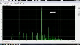
First off just so we are on the same page here is the circuit for reference.
In the perfect world with all mosfets and jets having truly symmetric properties then yes, you would have an in phase 2nd harmonic.
Best way to confirm with 100% certainty, is go back to your spreadsheet and where you have a column for trimpot turns add another column for R3 and another column for R4.
At each turn value measure the resistance for R3 and R4. Now you have a reference for source resistance of R3 and R4 and H2 value.
You will see at some point there is a minimum H2 value (most Negative) on either side of that value you have an in phase and out of phase Harmonic.
At that minimum H2 value as you reduce the value of R3 further you will have an in phase second harmonic and reducing it further will see the H2 value increasing.
Turning the trimpot in the opposite direction from that H2 minimum point so that R4 is decreasing in value will produce an out of phase H2 harmonic.
If it is not too much trouble, perform the measurements as described above and upload the excel spreadsheet again.
It will be highly informative for everyone.
Last edited:
Thanks Kevin. This is useful.
Are your Jfets closely matched?
Hi all,
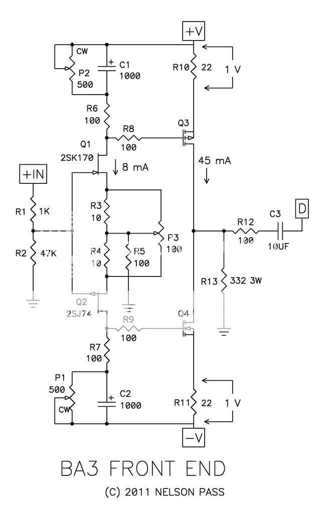
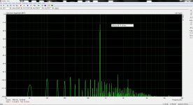
last days I was playing with P3 on the F5 power amp.
I dont have possibility to see distortion in time domain, so I listening and looking on the FFT.
FFT of what sounding best for me is in attachment.
That setup giving dominant 3rd on 8ohms and same setup on 4 ohms giving
dominant 2nd on low output voltage, until around 4.5Vrms, where 2nd and 3rd are equal, over 4.5Vrms 3rd became dominant.
4th harmonic is minimised, maybe there is clue....? Who knows....
When 2nd is nulled it sound to detailed for me I cant relax with that sound.
Attachments
Are your Jfets closely matched?
Sorry I didn't see this post. Yes, I got them from spencer, they are a closely matched quad at 7.6ma.
Last edited:
Here's what I'm talking about with my trim pots...all six are facing the same direction rather than being mirror imaged like the boards. When mine were set to the half way point they weren't the same channel to channel. I would suggest anyone using the BA-3 put their trim pots in mirror imaged.

- Home
- Amplifiers
- Pass Labs
- Adjusting P3 - a video