Try a series resistor for dropping the voltage to your fan. If it doesn't start up, a paralleled cap with the resistor might help.
What value resistor/capacitor would you suggest? I'm still rather wet behind the ears with ohm's law :S
24v down to 12v, hmmm...
Do you know the current draw (or power consumption) of your fan? If so, you want a resistor value that draws exactly the same as your fan when supplied 12V.
So for an example, suppose the fan takes 100mA from 12V. Then the series resistor you need must also take 100mA from 12V, which corresponds to 120R. At a guess the paralleled cap could be a 100uF, 35V but try without first, it might not be necessary. In this case, the resistor should be 2W rated as a minimum and it'll get quite hot.
You're saying that 10W @ 24V is lower power than 4W @ 12V? Those figures are the maximums, onset of clipping.
So for an example, suppose the fan takes 100mA from 12V. Then the series resistor you need must also take 100mA from 12V, which corresponds to 120R. At a guess the paralleled cap could be a 100uF, 35V but try without first, it might not be necessary. In this case, the resistor should be 2W rated as a minimum and it'll get quite hot.
You're saying that 10W @ 24V is lower power than 4W @ 12V?
Wouldn't it then just be easier to go with a simple power regulator (i.e. lm317t)?In this case, the resistor should be 2W rated as a minimum and it'll get quite hot.
No, the latter is less power than the former. I just understood that as the input voltage decreased, so did the available power output. You're saying that, as I thought I understood before, lower voltage will simply lead to a lower power that can be played without distorting.You're saying that 10W @ 24V is lower power than 4W @ 12V?Those figures are the maximums, onset of clipping.
Wouldn't it then just be easier to go with a simple power regulator (i.e. lm317t)?
To me, easier means fewer parts, less soldering. So yes, you can certainly do this with an LM317 - it will be more expensive and more parts, more soldering. A 7812 would be fewer parts than the 317, but the resistor will still easily win on price because the reg'll need a heatsink.
I just understood that as the input voltage decreased, so did the available power output. You're saying that, as I thought I understood before, lower voltage will simply lead to a lower power that can be played without distorting.
Yes.
Replace the resistor between the optocoupler with a potentiometer then adjust until 24V becomes 12V.
How would that work?
How would that work?
I'm no SMPSU design expert but I don't think it would.
It appears that, to some extent, the blind are leading the blind here. These power supplies are carefully engineered to do a specific job, and modifications ask for trouble.
The 24 V is regulated via, probably, an optocoupler that senses the output voltage, compares it to a reference, and controls the FET duty cycle accordingly. If you want to change the voltage, you need to muck with the feedback network. Sometimes there is a potentiometer but most often it's a resistor network. Sometimes there is a place to trim that network to finely adjust the output, and sometimes not.
Your job is to find that network and experiment with it. Shoot me a diagram and I will try to guess which components to vary.
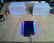
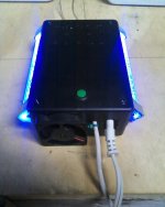
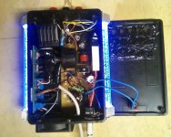
Abraxalito, I would shake your hand if I could meet you in person. Thank you for the great help! I wired in 100 ohm + 50 ohm resistors (10w, the only ones I could find over 1/4w at rat shack) and the fan runs great. Heatsink is actually very cool; the intake vents are right over it. I also resolved the noise issue; grounding the potentiometer case >.> I should have thought of that before!
I'm getting literally zero noise from the SMPS, and I left it stock with 24v and 3.3v out.
Really truly, thanks everyone who posted. Finished just in time!
Cheers,
-Patrick


I'm getting literally zero noise from the SMPS, and I left it stock with 24v and 3.3v out.
Really truly, thanks everyone who posted. Finished just in time!
Cheers,
-Patrick


- Status
- This old topic is closed. If you want to reopen this topic, contact a moderator using the "Report Post" button.
- Home
- Amplifiers
- Power Supplies
- Adjusting a SMPS output