Hi,
well, one may call it a subtractive filter, since the HP ist generated by taking the difference of Input signal and Lowpass (TFhp=1-TFlo).
On the other hand is the TF of the Lowpass generated by ´analog computing´ or state variable function.

If only there were a 2´nd order HP!?!
The somehow weird thing with this kind of filter is, that all depends on each other. Without the integrators there wouldn´t be any HP function, which -integrated a couple of times- results in the corresponding LP.
So, no HP wo LP and no LP without the HP.....sounds a bit like a dog chasing its tail, eh?
well, one may call it a subtractive filter, since the HP ist generated by taking the difference of Input signal and Lowpass (TFhp=1-TFlo).
On the other hand is the TF of the Lowpass generated by ´analog computing´ or state variable function.
Just to fan confusionEssentially the output of a 2'nd order high pass filter is...
If only there were a 2´nd order HP!?!
The somehow weird thing with this kind of filter is, that all depends on each other. Without the integrators there wouldn´t be any HP function, which -integrated a couple of times- results in the corresponding LP.
So, no HP wo LP and no LP without the HP.....sounds a bit like a dog chasing its tail, eh?
UUUh... UUuuuuuuuhm. Now i'm a "little" overwhelmed. I must really say that i just can't quite follow what you're going on about here. But please DO go on, maybe something cool comes out?
Anyways, in the meantime i've been reading a few OpAmp datasheets trying to find a cost-effective yet well-suited choice for this schematic.
@Andrew T.: I do understand that i have to do the matching, still, my preferred german parts supplier carries 0.1% resistors for a good price, so why not just use them? Capacitors i would've planned on hand-matching.
Also, about OpAmps, is there something you could recommend for this usecase?
@Calvin: At what frequencies did you start getting those oscillation problems? I would like to use this circuit as a base for subwoofer crossovers, so crossover frequencies at 50-100Hz should be possible.
Anyways, i've updated the schematic and pcb, which both can be found on:
ActiveCrossOver - Adjustable active 24db LR crossover
in the eagle 6 format (ltspice files as well!) For convenience, here's the images of both:
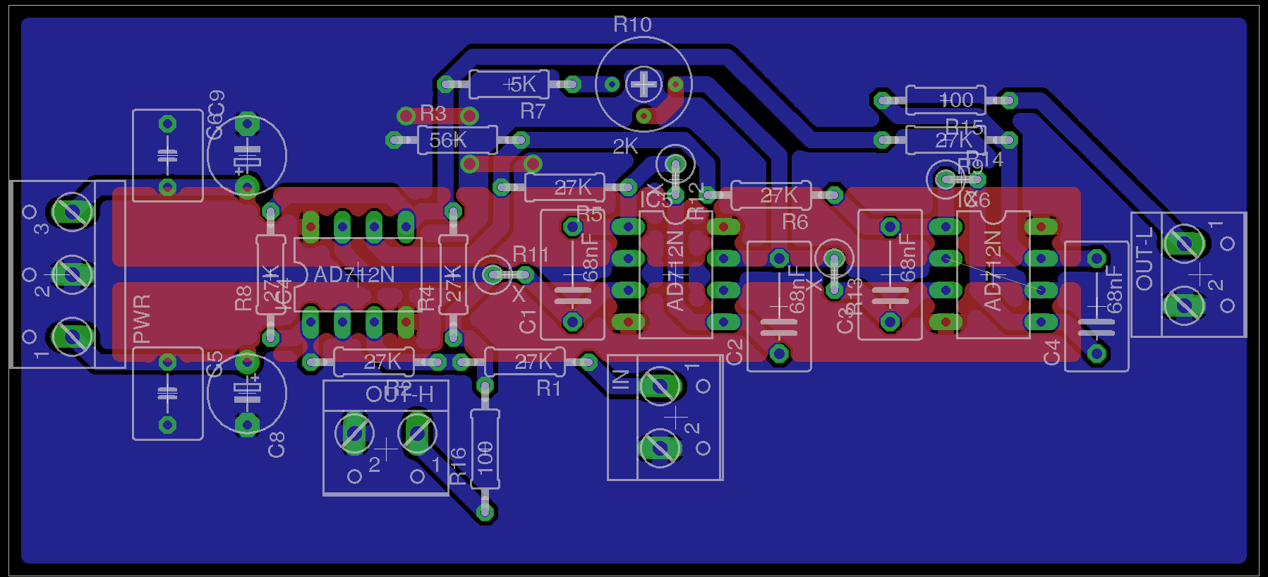
What do you think of this pcb design? Any good for this? Comments and Critique *warmly* welcome!
As a sidenote, the R11-R14 are drawn as verticalized resistors because i wanted to use those 2-pin-ic-socket-like-thingies so i could just plug 4 new resistors in to change the crossover frequency ...?
Thank you so much for your help up to here. Regards
- NebuK
Anyways, in the meantime i've been reading a few OpAmp datasheets trying to find a cost-effective yet well-suited choice for this schematic.
@Andrew T.: I do understand that i have to do the matching, still, my preferred german parts supplier carries 0.1% resistors for a good price, so why not just use them? Capacitors i would've planned on hand-matching.
Also, about OpAmps, is there something you could recommend for this usecase?
@Calvin: At what frequencies did you start getting those oscillation problems? I would like to use this circuit as a base for subwoofer crossovers, so crossover frequencies at 50-100Hz should be possible.
Anyways, i've updated the schematic and pcb, which both can be found on:
ActiveCrossOver - Adjustable active 24db LR crossover
in the eagle 6 format (ltspice files as well!) For convenience, here's the images of both:
What do you think of this pcb design? Any good for this? Comments and Critique *warmly* welcome!
As a sidenote, the R11-R14 are drawn as verticalized resistors because i wanted to use those 2-pin-ic-socket-like-thingies so i could just plug 4 new resistors in to change the crossover frequency ...?
Thank you so much for your help up to here
. Regards- NebuK
Last edited:
Hi,
I wouldn´t recommend the filter below ~200Hz. But I didn´t try to compensate the circuit since I changed to a different topology that I found alot more practical. As said before, a filter without equalizer is hardly good for anything.
So its all up to a test, if You experience oscillation probs or not.
As Opamps You might use the all present NE5532, or more costly the LME-Seeries or AD797, all of bipolar type.
Alternatively You may consider types with FET- or JFET-Input. Due to the highly varying impedance values in filter circuits FET (or JFET) OPamps hold a slight advantage over bipolars.
The OPA134/2134/4134 or their cheaper brethren 132/2232/4232, the OPA604/2604, or AD711/712 are relatively cheap and well sourceable JFET-OPs.
If it were for high quality but costly the AD8610/8620 or OPA627 come to mind.
jauu
Calvin
Last edited:
I don't follow the math, but the idea seems to work fine for odd-order filters as well. Here's a nice simple 3'rd order Butterworth.Mathematically they exploit the fact with filters of even order (2nd, 4th, etc.) the denominator of the transfer functions of Highpass and Lowpass are the same. The TFs only differ in the numerator.
Attachments
On second thoughts, I don't see a reason for low frequency oscillation. Was it high frequency instability or low frequency motorboating? Roughly what was the frequency of oscillation?While the filter worked well at frequencies of a couple of hundreds Hz on, I sometimes got oscillation effects with low crossover-frequnecies.
It's probably a good idea to increase the capacitors then, perhaps to 100nF. IMHO, a good rule of thumb is to keep the resistors between 10K and 100K.I would like to use this circuit as a base for subwoofer crossovers, so crossover frequencies at 50-100Hz should be possible.
Heyyas,
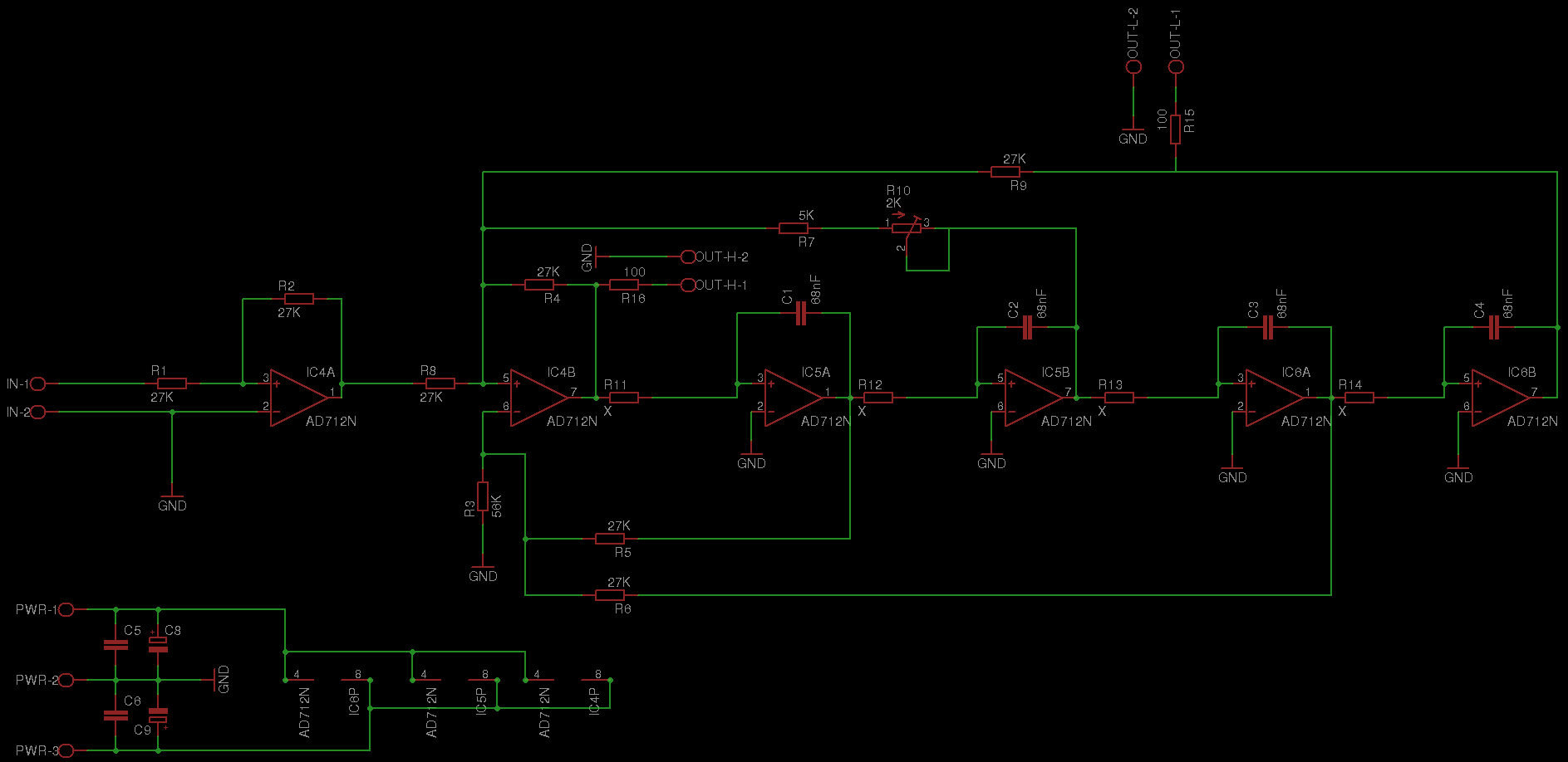
i've once again found a little time to tune the capacitor values and play around a little. I've also refined the PCB a bit. So once again, here's the board layout and schematic:
http://pics.kanojo.de/acrossover-schematic.png
http://pics.kanojo.de/acrossover-pcb.png
(the opamp name is just for reference, eagle just happened to have it, i think i'll go with the opa2134 as you advised. I already quite like it in my CMoy).
So, the 68nF gives me the following:
15K 155Hz
22K 106Hz
33K 70Hz
47K 49Hz
68K 34Hz
82K 28Hz
100K 23Hz
Which is just E10 + 82K + 100K. A set of four of each for tuning my woofer crossover (roughly) shouldn't be that bad, right? So that later when more refinement is needed one knows where to look for intermediate values...
Sure, for a general 2-way crossover where the crossoverpoint is somewhere from 1500Hz to 4000Hz, i'd need different capacitor selection to have a nicely adjustable range somewhere up there.
But for now ... do PCB and schematic look ok? Do you have any other advise on how to improve it? Do you think i could maybe get the PCB simpler and more home-etchable by using 4x or 8x opamps (i guess today the crosstalk between the channels is negligible for my application?)?
Anyways, thanks alot once again! Regards
- NebuK
PS: Eagle and LTSpice files are again on ActiveCrossOver Git Source Tree - Adjustable active 24db LR crossover ...
i've once again found a little time to tune the capacitor values and play around a little. I've also refined the PCB a bit. So once again, here's the board layout and schematic:
http://pics.kanojo.de/acrossover-schematic.png
http://pics.kanojo.de/acrossover-pcb.png
(the opamp name is just for reference, eagle just happened to have it, i think i'll go with the opa2134 as you advised. I already quite like it in my CMoy
).So, the 68nF gives me the following:
15K 155Hz
22K 106Hz
33K 70Hz
47K 49Hz
68K 34Hz
82K 28Hz
100K 23Hz
Which is just E10 + 82K + 100K. A set of four of each for tuning my woofer crossover (roughly) shouldn't be that bad, right? So that later when more refinement is needed one knows where to look for intermediate values...
Sure, for a general 2-way crossover where the crossoverpoint is somewhere from 1500Hz to 4000Hz, i'd need different capacitor selection to have a nicely adjustable range somewhere up there.
But for now ... do PCB and schematic look ok? Do you have any other advise on how to improve it? Do you think i could maybe get the PCB simpler and more home-etchable by using 4x or 8x opamps (i guess today the crosstalk between the channels is negligible for my application?)?
Anyways, thanks alot once again
! Regards- NebuK
PS: Eagle and LTSpice files are again on ActiveCrossOver Git Source Tree - Adjustable active 24db LR crossover ...
Hm, i certainly won't fear a bit higher building cost if it improves performance ... for this i've tried to adopt what godfrey posted
thanks
- NebuK
... doesn't that apply here for some reason? Also, could you give a little beginner like me a little hint why larger resistors in this schematic will promote noise? By intuition i would've thought otherwise ;/a good rule of thumb is to keep the resistors between 10K and 100K.
thanks
- NebuK
Self's latest filter implementations go the whole hog and reduce the resistances such that paralleled opamps are required to drive these low loads.
But if you go back to Ben Duncan where he adopted 8k, 10k and 12k as typical resistances to keep noise lowish, then you probably would be OK.
I would tend to look at the range 5k1 to 12k for the filter resistors in a wideband filter set up. Bass only may tolerate much higher noise.
But if you go back to Ben Duncan where he adopted 8k, 10k and 12k as typical resistances to keep noise lowish, then you probably would be OK.
I would tend to look at the range 5k1 to 12k for the filter resistors in a wideband filter set up. Bass only may tolerate much higher noise.
Fair point about the noise. The thermal noise of a 100K resistor is 10dB higher than a 10K resistor i.e. about twice as loud. That's not the whole story, though.
Firstly, there are plenty of other sources of noise in the circuit besides the filter resistors so reducing them, even by a factor of 10 won't have that much of an effect on the noise unless everything else is tackled as well.
Secondly, and more importantly, is that the lower the load impedance on an opamp, the higher the distortion. That is particularly important in this circuit because the opamps aren't just driving the resistors. The last 4 opamps are directly driving the filter capacitors.
As it is, you're using 68nF caps, which is already a very heavy load for the opamps, and if you want to reduce the resistors, you will need to increase the capacitors.
Bear in mind that while 68nF represents an impedance of 33K at 70Hz, it is only 330 Ohms at 7KHz, and not much over 100 Ohms at 20KHz. That's quite a nasty load for an opamp.
~~~~~~~~~~~~~~~~~~~~~~~~~~~~~~~~~
edit: Oops, I forgot to mention - It looks like there's a couple of errors in the schematic:
A) R15 (the OUT-L1 connection), should be connected to the other side of R9, i.e. directly to the output of IC6B.
B) The center pin of the potentiometer (R10) should not be connected to ground. It should be connected to either pin 1 or pin 3.
Last edited:
Hey,
thanks for your replies! I think in the case of the resistor range i'm going to be in ... best would to be just to build it and toy around?
I'll also try to get around and find so informations on error accounting like this that a beginner like me can understand ;P maybe i can come up with a nice way of finding the right balance on this tightrope walk?
For the schematic errors, i've fixed them here i think ... as i'm still very unsure about all of this, could you maybe check them again?
http://pics.kanojo.de/acrossover-schematic.png
http://pics.kanojo.de/acrossover-pcb.png
Thank you so much for your help! Regards
- NebuK
Yes, that looks right, and I agree about build now, fiddle around later. It's too easy to get trapped into "paralysis by analysis".For the schematic errors, i've fixed them here i think ...
- Status
- This old topic is closed. If you want to reopen this topic, contact a moderator using the "Report Post" button.
- Home
- Source & Line
- Analog Line Level
- Adjustable Linkwitz-Riley filter: Help needed with SPICE