Probably, it's the same family as the AD1862:philbyx said:I want to know if I can supply it with +- 12 V in the analog part.
http://166.111.64.217/datasheet/analogdevice/PDF/1068.pdf
/Hugo
Dear Philippe,
hope this helps:
http://www.audioasylum.com/images/DITBschematic.pdf
http://www.audioasylum.com/images/DITBMOD.pdf
datasheet for ad1851/61 (they aare pin compatible with ad1856/60)
http://166.111.64.217/datasheet/analogdevice/PDF/1064.pdf
hope this helps:
http://www.audioasylum.com/images/DITBschematic.pdf
http://www.audioasylum.com/images/DITBMOD.pdf
datasheet for ad1851/61 (they aare pin compatible with ad1856/60)
http://166.111.64.217/datasheet/analogdevice/PDF/1064.pdf
Yes Jean Paul, you are right !
<<The AD1851/AD1861 is available in either a 16-pin plastic DIP
or a 16-pin plastic SOIC package. Both packages incorporate
the industry standard pinout found on the AD1856 and
AD1860 PCM audio DACs. As a result, the AD1851/AD1861
is a drop-in replacement for designs where ±5 V supplies have
been used with the AD1856/AD1860>>
This suppose that the 1860 can be used with more than 5 V, like the 1862.
Thanks
Philippe
Got it!
Hi,
Got it (i have the original datasheet books), now looking at audio/video ref manual 1992. But i don't own a scanner
Anyway:
+-5 to +-12V operation. -Vdigital may not be more negative than
-Vanalog!
You can use it as voltage out +-3V or current out +-1mA by not using the internal opamp. Maybe room for improvements..!
Currents drawn are 10.5mA for + at 12V, 13.5mA for - at -12V, only specified analog and digital together (me thinks).
Currents are at 10MHz clock.
Versions from "bad" to "good" (THD figures):
dip: N N-J N-K
smd: R R-J R-K
Optional MSB adjust:
pin 15 - 470k - pot 100k - 200k - pin 1
then pin 14 to wiper of pot
Decouple all supplies to dgnd or agnd (duh).
Example schematic shows NJN5532 or AD712 for a low pass filter


And it's a 18 bit device
pins
1 -V analog
2 logic gnd
3 logic +V
4 nc
5 clk
6 le
7 data
8 logic -V
9 Vout
10 feedback resistor
11 summing junction
12 agnd
13 Iout
14 msb adjust
15 trim
16 +V analog
input 2's complement 18 bit MSB first. Inputs are clocked on rising edge of clk. After loading the bits an active high le pulse .
Gr
Hi,
Got it (i have the original datasheet books), now looking at audio/video ref manual 1992. But i don't own a scanner
Anyway:
+-5 to +-12V operation. -Vdigital may not be more negative than
-Vanalog!
You can use it as voltage out +-3V or current out +-1mA by not using the internal opamp. Maybe room for improvements..!
Currents drawn are 10.5mA for + at 12V, 13.5mA for - at -12V, only specified analog and digital together (me thinks).
Currents are at 10MHz clock.
Versions from "bad" to "good" (THD figures):
dip: N N-J N-K
smd: R R-J R-K
Optional MSB adjust:
pin 15 - 470k - pot 100k - 200k - pin 1
then pin 14 to wiper of pot
Decouple all supplies to dgnd or agnd (duh).
Example schematic shows NJN5532 or AD712 for a low pass filter
And it's a 18 bit device
pins
1 -V analog
2 logic gnd
3 logic +V
4 nc
5 clk
6 le
7 data
8 logic -V
9 Vout
10 feedback resistor
11 summing junction
12 agnd
13 Iout
14 msb adjust
15 trim
16 +V analog
input 2's complement 18 bit MSB first. Inputs are clocked on rising edge of clk. After loading the bits an active high le pulse .
Gr
The 1862 has a 'digital offset circuit'. Think it is patented, the databook talks about patents which are not for the 1860.
numbers 4.349.811 4.857.862 4.855.618 3.961.326 4.141.004 4.902.959.
It shifts the midscale output away from the point of msb transition.
No internal opamp as in the 1860. Different pin-out obviously.
So i think they are quite different apart from 18-20 bit.
Regards,
numbers 4.349.811 4.857.862 4.855.618 3.961.326 4.141.004 4.902.959.
It shifts the midscale output away from the point of msb transition.
No internal opamp as in the 1860. Different pin-out obviously.
So i think they are quite different apart from 18-20 bit.
Regards,
vasiltech said:
Thank you very much
URL is death. I will attached here.
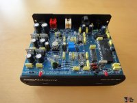
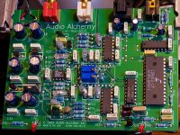
What about the sound character of this DAC device from Audio Alchemy ?
Attachments
Last edited:
Hello, here is the actual link:URL is death.vasiltech said:has placed it here:
www.vasiltech.nm.ru/files
vasiltech.narod.ru/files.htm
Last edited:
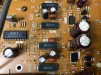
Can anyone tell me if these chips in the photo are the same asad1860n-k? The chips are printed ad1860-k. The datasheet of the ad1860N does not have this type. They are used in a sony player in parallel with 2 chips per channel. I am wondering why Sony did not implement dual differential mode.
Attachments
- Status
- This old topic is closed. If you want to reopen this topic, contact a moderator using the "Report Post" button.
- Home
- Source & Line
- Digital Source
- AD1860 datasheet for Audio Alchemy DAC