It is actually common mode input that I meant when I wrote about offset ... Think it is time for a holiday.....
Regards
Charles
I think tying down both the input nodes with a resistor to ground is needed to keep VCM in range of opamp.
regards,
Kanwar
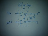
I was once thinking about a different compensation method using an OP-AMP in inverting setup. The input is going to the Supply rail and the output is going to the two input nodes via a resistor in order to compensate for the common mode voltage. I can make a drawing if it is unclear wha I mean.
Regards
Charles
Regards
Charles
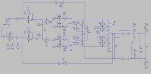
Due to the lack of an op-amp symbol with differential outputs I took a normal one - but I think this shouldn't give too much problems for the interpretation of the circuit's workings.
On the left we have the differential audio inputs. We can also see the two NFB inputs with the lead compensation.
The inverting input of the auxiliary op-amp at the lower part of the diagram is fed with the rail voltage which is then inverted and fed to the two inputs. The circuit does nothing else than subtract a voltage - proportional to the rail voltage - from the two inputs (to be more correct it does actually subtract current). It shouldn't be too difficult to find out how it should be dimensioned (we don't have to hint the copiers from china to everything - do we ?). In the drawn form it can be used for the situations where the negative rail of the power stage is at the same potential as the ground of the input and modulator circuitry. If the input circuitry's ground is above that (if for instance its negative rail = negative rail of the output stage) it has to be completed with an additional resistor.
Regards
Charles
Thanxz Charles,
Nice explanation.
Got its working now, sure we don't want to attract copycats from far-east lands. The subtraction should be done in such a way that the input voltage range should be within input common mode voltage range of the opamp, in other words it looks like string puller
The fully differential opamps chips we have in market have a dedicated pin called VCM for setting up the offset at their output, Is this of any help here.
http://www.national.com/ds/LM/LME49724.pdf
regards,
Kanwar
Last edited:
Another modulation scheme
I would first like to remind people (because of the loose terminology in the ecler article)
Here's a thought, so far this thread has covered AD (bilevel) and BD (trilevel). How about more than three rails, Class G style?
To give an example of the idea, let's say we have five rails (Class G amplifiers have at least four), and so output pluses so as to create the following characteristics:
*As with BD modulation, pulses do not appear in absence of an audio signal.
*For the lower quadrants (lower portions) of the positive half cycle, positive pulses "+1" appear, and for the upper quadrants (upper poritons), the switching is between "+1" and "+2.
*During lower quadrants of negative half cycles of the modulating audio signal, negative pulses "-1" appear, and during the upper quadrants, the switching is between "-1" and "-2."
Another scheme which I have recently seen in an industrial drive was 5 level modulation scheme they constructed using Neutral Point Connect Halfbridges in which the levels were +2,+1,0,-1,-2. But does it have any substantial advantage for class-D remains a question for sure.
Another scheme which I have recently seen in an industrial drive was 5 level modulation scheme they constructed using Neutral Point Connect Halfbridges in which the levels were +2,+1,0,-1,-2. But does it have any substantial advantage for class-D remains a question for sure.
Application of Semiconductors with low breakdown voltage at high dc-link voltages and vast output powers?
Actually some months ago I had the innovative idea to construct a 3-level NPC fullbridge Class-D amplifier. Just for fun. Haven't started yet, probably never will

Currently working on 3-Level self-oscillating BD mode single rail design using FGH50N3 IGBTs , tweaking of common mode filter is going on.
YES
Currently working on 3-Level self-oscillating BD mode single rail design using FGH50N3 IGBTs , tweaking of common mode filter is going on.
LIKE THAT
Attachments
Who would trade overall EMI performance for eliminating carrier residual only when there is no signal?
Carrier residual applied to speakers is completely harmless. EMI can potentially disturb any piece of electronics around.
Class BD means "wrong design goals". Low EMI should be the first goal.
Class BD has high common mode needs a extra filter for that but it doubles the carrier.
I have a self oscillation done some time ago, did has quite low distortion, I do like also the 5 level one.
But now busy with home renovation and the start with circlotron. and the help for a friend who did contract breast cancer.
regards
Attachments
Class BD has high common mode needs a extra filter for that but it doubles the carrier.
regards
That is where the common mode inductors come in to play.
That is where the common mode inductors come in to play.
Yes I now, it is tricky calculating right.
here I did use one in past, when circlotron is ready I go class D because parts get better and better.
regards
Attachments
Make it post filter feedback !
I have ask myself al the time, because I do not like feedback if pre feedback has also impact on sound, or can I see the prefeedback who do only correct the switching action of amp as a open loop with the more open sound.
When using a postfeedback alone I get a fase shift and then the doubling of the carrier do not happen, also the 3 level do not work, when do use both I think it is not as precise also, so I do need a triangle carrier when do only postfeedback.
I have to test in future, this is a old project and I need to go on with the autobias cicrlotron.
regards
- Status
- This old topic is closed. If you want to reopen this topic, contact a moderator using the "Report Post" button.
- Home
- Amplifiers
- Class D
- AD Vs BD Modulation in Class-D