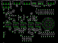
Thats better. I dont know if it is correct or not, but when you start at the lower let corner of the lay out (last post). There are 3 'large' holes above each other. If you start halfway the lowest 2 and you move to the right, you reach another 'large' hole. Just to the right of that there is a copper track (nearly) touching an copper island. It seems this is not supposed to be, but you might not be able to etch (how do you spell that??) that fine, so try to move it away a bit if you can or make sure ther is no shortcircuit after finishing the board.
One last point: there are a few corners where you have angles smaller than 90 degrees, try to prevent that, you might get sparks and burn you're board.
Besides that, I have no comment, it looks ok to me.
Greetz Mark
One last point: there are a few corners where you have angles smaller than 90 degrees, try to prevent that, you might get sparks and burn you're board.
Besides that, I have no comment, it looks ok to me.
Greetz Mark
Markje said:One last point: there are a few corners where you have angles smaller than 90 degrees, try to prevent that, you might get sparks and burn you're board.
 Why would he get sparks? It's low current and voltage.
 but it the power supply voltage was at kV's level it would have been true.
Current has nothing to do with it. Neither does voltage. In a corner the distance between the two tracks gets smaller as you reach the inside of the angle. It goes to zero. That means that no matter what voltage, you get a spark trough the air. I dont know the correct english term for it for this event, but lightning is based on the same priciple; when voltage is high enough and/or distance small enough, you get a spark. In order make a spark jump form 1 track to the other, you need about 10.000V per cm of air you cross (in rather dry air). When the distance reaches zero, so does the required voltage. So, you get a voltage drop between two parts of the track with a certain resistance. The current is limited by I=U/R, but it is a spark and will burn the track.
Another example: a switch that is not suited for DC but is used for it, the contacts will burn, even though the current delivered by the power supply is not very high.
There is a fysics test with 2 metal pins. When put up staight, bend the end way from each other and put an power supply (with an certain voltage, to make the spark) at the bottom, you see a spark moving from the bottom to the top of the pins, getting longer as the pins are further from each other. At the top you have the same voltage (at school, we've seen it with 500V), even though the distance is about 30cm (1 feet). In the air, not in vacuum or something else, normal air.
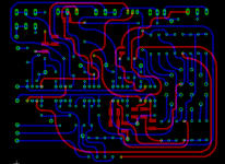
You can check any professional PCB, no angles smaller than 90 degrees are used, they al use 2 45 degree angels. That is also why round tracks are best, then there are no angles, zoomed in, only straight tracks.
The only 90 degree angle that works, is with an island in the corner. in that case there are 90 degree angels, but they dont give any problems (don't ask me why, I forgot).
You can check any documentation on designing PCB's for it. I haven't forgotten everything I learned.
It doesn't happen every time, certain demands have to be met, but it can happen at any voltage, any current when the angels are wrong. It's an easy problem to prevent, any right angel can be changed.
Greetz Mark
Another example: a switch that is not suited for DC but is used for it, the contacts will burn, even though the current delivered by the power supply is not very high.
There is a fysics test with 2 metal pins. When put up staight, bend the end way from each other and put an power supply (with an certain voltage, to make the spark) at the bottom, you see a spark moving from the bottom to the top of the pins, getting longer as the pins are further from each other. At the top you have the same voltage (at school, we've seen it with 500V), even though the distance is about 30cm (1 feet). In the air, not in vacuum or something else, normal air.
You can check any professional PCB, no angles smaller than 90 degrees are used, they al use 2 45 degree angels. That is also why round tracks are best, then there are no angles, zoomed in, only straight tracks.
The only 90 degree angle that works, is with an island in the corner. in that case there are 90 degree angels, but they dont give any problems (don't ask me why, I forgot).
You can check any documentation on designing PCB's for it. I haven't forgotten everything I learned.
It doesn't happen every time, certain demands have to be met, but it can happen at any voltage, any current when the angels are wrong. It's an easy problem to prevent, any right angel can be changed.
Greetz Mark
k1jroth said:What about my step by step LP how does it react if it`s turned when power is on? (rotary switch)
This switch must be make-before-brake type.
Also, you mix signal and power ground, what isn't good.
R11?(10k) should be placed close to IC5.
Regards,
Milan
That sparking thing is interesting but I think irrelevant in this instance. Sparking occurs because the electricity is trying to find a path. In the case of the tracks, the current is already flowing round the very low impedance copper, so why should it want to jump across a tiny gap?
Some weeks ago I asked for some information from a professional pcb designer on what is a no no for audio. Particularly large fill areas and wide traces, which I prefer to use on my designs.
The comments I got were quite interesting, and I will list some of them:
1) Generally speaking, almost nothing matters with audio circuits.
2) There are no high-speed issues with audio.
3) Trace width doesn't matter. Trace width only matters if you are using a high enough current that you need the current carrying capacity of a wider trace.
4) Copper fills can cause noise coupling problems in high-speed circuits. I've never seen a slow (audio) circuit where it mattered.
5) What does matter with audio circuits is power system stability --- power supplies must be well decoupled so no power supply noise (particularly 50 or 60 cycle hum) can get into the audio circuit.
6) If there is a very sensitive front end (like a very sensitive pre-amplifier circuit) you might need to keep that separated from the other traces (and fills) to minimize external noise from coupling into that part of the circuit.
7) Otherwise, audio circuits are pretty forgiving.
Perhaps designing a shorter path, using curves, less than 90 degrees or 90 degrees, can improve audio specs a little (measured or subjectively), but I am not so sure about the shape itself. Doing a curve, a series of 45 degrees angles or 90 angles to get to a certain place with a slightly shorter trace may not be that important. In fact I think it is not.
Carlos
- Status
- This old topic is closed. If you want to reopen this topic, contact a moderator using the "Report Post" button.
- Home
- Amplifiers
- Chip Amps
- active filter