Hi,
that header is not my idea, I first saw it in Ben Duncan's 1981 article in HiFi News "A versatile active crossover"
The slight disadvantage with equal value S&K is the 8.2db gain that results from the 2pole Butterworth and +16.4db from a 4pole filter.
You have to throw away all this gain with attenuation (what a waste). Ben used active inverting attenuators on both input and output
The higher gain stage could be replaced with a 0db MFB to cut the overall gain of a 4pole to just +2.45db (instead of +16.4db). The two inverting MFB stages will cancel with the resulting output being in phase with the input in a 4pole filter.
Update: Futurlec has notified me that my order has be filled and shipped. I should receive it in about a week or so. That's good news.
Reading through Rod Elliot's article on bi-amping:
http://sound.westhost.com/bi-amp.htm
makes me think I should do as he says and use the 310Hz and 3100Hz as the crossover points. The 310Hz point is around the 50% power area - where bass to mid/high require about the same power. As I have six amps, but only 2 power supplies (one for both woofer channels and one for both pairs of midrange and tweeter), it makes sense to split the power requirements at this point.
Woofer can easily exceed 310Hz on axis response, midrange can be crossed as low as 250Hz and will will give smooth response >5000Hz.
Tweeter will sound sweet from 3100Hz and up.
Driver efficiency is within 2dB of each other (90 - 92)
If I haven't mentioned it before drivers are:
Woofer - Seas CA21REX(H333)
Midrange - Max Fidelity pro411m8
Tweeter - Scanspeak D2905/9300.
I got 'em!
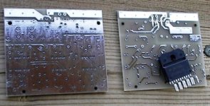
Ok, today I received the boards. They look good.
I am in the process of checking them against the final layout for mistakes. So far, so good.
Having read bad things about Futurlec, I must say that I am pleased with the service. I also ordered a few components with this, that would have cost double from Digikey.
I can safely recommend them, good to deal with.
Here's a shot of two of the boards, showing top and bottom. There's a LM3886 in front for perspective.
On my shopping list is a new camera, this one is a real pain to use for any detail. As grainy as they appear in the picture, the boards are very clean and well made.
Attachments
tubob said:
Hows the project going on?..
Hi Bob,
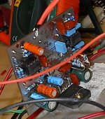
Last night I started to populate one of the low pass amps and got it about half done. Hopefully, I can complete assembling it tonight, ready for testing. I've got my fingers crossed.
")
One by one I'll have to assemble and test each unit, so it could take a while. Though the boards are small, they have a good number of components on them and barring any more of the mistakes that I made last night (installed 3-2.2k resistors instead of 22k!...thanks to Brian (BWRX) for convincing me to use a double sided board, they were easy to change witout trace damage.).
impsick said:wait you purchased those boards? they look like home etched. how much did you pay?
Yes, from Futurlec. The photo is not of great quality, so you really can't see how good these boards are. Through plated holes, very clean etch.
There is no silkscreen or soldermask.
They worked out to $3.10 each - I had 12 made.
Ok, less than a day.
Sometimes, I'll put something off if I have a feeling it might not work, to avoid disappointment. This being my first time having a board made for a project, I was especially anxious.
Just had it running on a single, unregulated +/- 18 volt supply - filter and amp...
It works, nothing but bass coming out of the speaker.
I will probably have enough done (get it installed in the chassis, wires routed) by tomorrow night for a full power test from the proper power supplies.
Brett, give me an email address, I'll send the files.
Attachments
Hi Troy,
Early on I decided that I would not use this idea (although very good). A tentative board layout confirmed what I expected - it really complicated the layout, plus increased the physical size of the board.
Given the compact layout that I did get, the cost is very low for each board, therefore not much lost if I decide to change the crossover frequency.
The filters are 4th order Linkwitz-Riley and I believe there is no need to explore other alignments (from my perspective). A 24dB / octave active filter will suit my every need, for 3-way and 2-way.
Update: I am slowly getting to the point where I can do a full power test on the first low pass unit.
I have added 6 RCA input jacks and the power cables to the chassis (temporary, need a better way to get removable power from the power supply chassis to the active amp chassis. Maybe Jones plugs)
I have the power supply chassis finished and it's in use powering my subwoofer amp, I'll need to get the active amp done enough to bring up here and plug into it.
Maybe a day or two.
Thank you very much.MJL21193 said:Brett and tubob, I have sent the files.
Full power test did not go well. In my haste to get it done, I must have formed a solder bridge, or there was a speck of solder on the board somewhere that shorted something.
Burned both NE5532's.
Disconnect, bring it back down to my lab, where I do what I should have done in the first place - build a temporary +/-35 volt power supply.
Examine the board over and over again. Disconnect wires, take out the op-amps. Check for shorts.
Put a new op-amp in the lowpass filter section. Re-route wires to just go through it, and not the buffer/volume control.
It's working again, very clear solid bass to my test speaker. Stops! Oops, forgot the heat sink. Thermal shutdown really works.
With the second op-amp in, I try again. Works! Louder - the volume control buffer has a gain of two. The slide pot gives very linear, smooth volume control.
DC offset at the speaker output is ~22 millivolts. Given the fact that some of the components for this first board were salvaged from old circuit boards, it's not bad.
Given the chance to do it again from the start, I would make some changes.
First: screw terminal blocks. Would make things so much easier.
Second: solder mask. It's very difficult to solder a board this small without bridging to the next trace.
Some mistakes in my schematic: R14 should be 10K. Although not in the schematic in post#1, C18 and C19 bypass to ground for op-amps should be 10uF/25V.
Have put this on hold for the moment to concentrate of the speaker building aspect of this project. Details here:
http://www.diyaudio.com/forums/showthread.php?s=&postid=1277692#post1277692
I also have been compiling a list of items I need from Digikey. Seems every time I make an order, I forget something.
So far I have 18 items on the order. Some of it is for these amps, some for the speakers (banana jacks, banana plugs) and others for future projects (namely a higher power SymAsym)
On my prototype board pictured earlier, I used bipolar caps (salvaged from an old circuit board) for DC blocking/isolation. I'm thinking I'd be better off with high value poly caps, and to eliminate C10, which is between the volume buffer and the amp.
Anyone with any thoughts, recommendations on this?
Brett said:I'm ordering 30 for use
Hi Brett,
A word of caution: I've only tested the low pass portion, not the bandpass or the highpass. You might want to either wait till I do these trials or scale down your order and try a few for yourself.
There are no obvious reasons why they wouldn't work but with my luck, you never know.
Also, keep me posted on your results.
- Status
- This old topic is closed. If you want to reopen this topic, contact a moderator using the "Report Post" button.
- Home
- Amplifiers
- Chip Amps
- Active filter plus LM3886 - one board