Thanks for your reply.
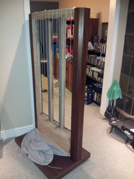
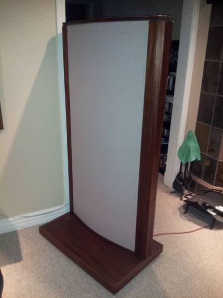
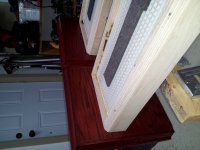
It's Spectra 11's. I've made floor stands for the ESL panels and removed the original woofer boxes so I want to have as small panels as possible both for esthetical reasons and to decrease the distance to my woofer towers which are placed beside the panels.What model Acoustat are you working on? Also, what is your goal in making slimmer frames?
I have considered building an aluminium frame, but I'm a bit worried about resonances in the metal (maybe it's not an issue?). The other option I've considered is to glue together two bars of 40x22 mm MDF board on each side of the panel in an L shape and screw the panels directly to the "back bar".If you are planing on a wooden frame, slimmer than original, then you may end up with a rather flimsy arrangement. A frame of metal (which has its own problems) may be slimmer and yet rigid enough.
Ok, I'll better keep them then.The felt blocks on the rear of the panel are there to tame resonances. I recommend that they be retained, although some people have removed them and they are okay with the result.
Yes, I think you're right, it's probably not a burn mark but discolouration and black coating sticking out between the plastic panels.The dark area around the bias feed wire may not be a burn mark - it's hard to tell from your photo. The panel does look like it has discolored quite a bit, which is not unusual: the high voltage tends to attract dust and especially smoke particles. The dark area may be just an accumulation of dirt, or it may even be a stray bit of conductive coating that got slopped on the edge of the panel during original manufacture.
I've been toying with the idea of making new smaller, but more ridged frames for both my Model 3s, and Spectra 11s. My plans have been around using a steel tubing with rectangular cross section, and filling it with lead shot for damping. I'd then pull a cloth sock over them, like stock, and add a thin wood strip "picture frame" around the whole thing. I got the idea from the Arcici stands on my ESL-63s... I might even try to bend the tubing to work as a stand as well. Still mostly just ideas floating in my mind at this point, but thought I'd share, since it sounds like you're working towards a similar goal.
Hello Andy:
I'm the original owner of a pair of 2 + 2's. They were in working condition when taken out of service about 7 years ago. They've been stored inside the entire time. I'd like to replace the grille cloths on them and put them back in service.
Is there anything I should be aware of/do to these first? It seems like now would be the time to do so.
Thanks.
Everett
Hi Everett, the original grill cloth can be found here.
The Upholstery Company Inc. Fine Upholstery Service | Mesa AZ | Tempe AZ
Anyone here know the impedance of Acoustat X's with blue medallion transformers? I have a FM Acoustics 600A amp that will drive a 2 ohm load but suggests a cap/resistor if the speakers are under 4 ohm load with no signal.
Thanks
All Acoustats are 4 ohms.
All Acoustats are 4 ohms.
Thank you. I'm going to try the FM Acoustics amp on them and see what happens.
I've been toying with the idea of making new smaller, but more ridged frames for both my Model 3s, and Spectra 11s. My plans have been around using a steel tubing with rectangular cross section, and filling it with lead shot for damping. I'd then pull a cloth sock over them, like stock, and add a thin wood strip "picture frame" around the whole thing. I got the idea from the Arcici stands on my ESL-63s... I might even try to bend the tubing to work as a stand as well. Still mostly just ideas floating in my mind at this point, but thought I'd share, since it sounds like you're working towards a similar goal.
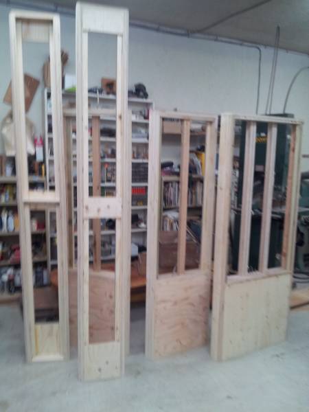
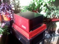
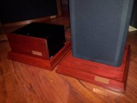
Here is a frame for the model 3 that i sold one month ago.
New frames for model 2s - 3s - 1+1s -
Last edited:
Here is a frame for the model 3 that i sold one month ago.
New frames for model 2s - 3s - 1+1s -
nice you do the after market support and upgrades
") frames look nice! like the wire idea with the fabric to create an arc!
frames look nice! like the wire idea with the fabric to create an arc!nice you do the after market support and upgrades
If you want info on ANYTHING regarding Acoustats take a look at my friend Jocelyn's work on my flickr photo page and send me an email if you want his email address.
PS: The monster panels are his Spectra 8800s DIY all steel frame 800 pounds each.
Flickr: mracoustat's Photostream
mracoustat@videotron.ca
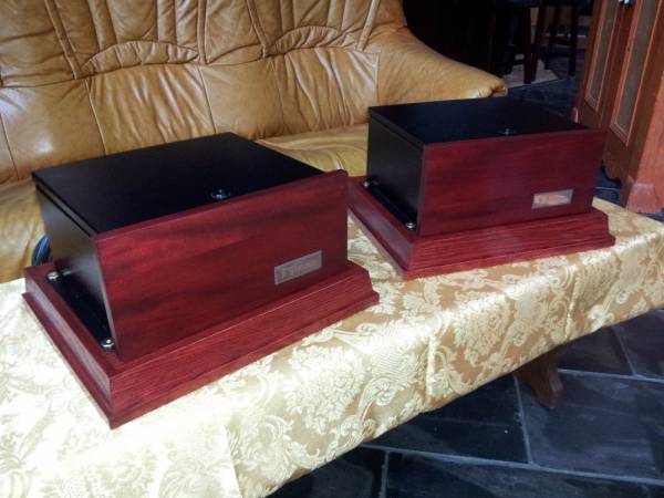
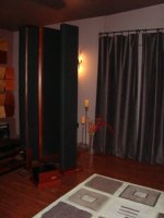
This is a pair of 1+1s leaving for Barbados this week, the interfaces are seperate to be next to the amps.
Attachments

Thanks for your reply.
It's Spectra 11's. I've made floor stands for the ESL panels and removed the original woofer boxes so I want to have as small panels as possible both for esthetical reasons and to decrease the distance to my woofer towers which are placed beside the panels.
Ok, I think I understand better now. When you say 'slimmer' frame, I now assume you mean the side-to-side distance. The width of the original Spectra 11/1100 frame was sized to fit the woofer box, so there is nothing 'magic' about its dimensions. As you have probably observed, the Acoustat single-panel-wide speakers (Model One and 1+1) had frames only wide enough to contain the panel plus the thickness of the wood side members.
Therefore, I would say 'full steam ahead' on making the frames of your choice, to match to your configuration. There are other posts in this series regarding metal frames, most of them containing sand or lead shot. Naturally, some extra care must be taken to insulate the panel from the frame, but it is certainly possible, and may be the best way to obtain a very thin supporting frame.
The acoustic distance between the front and back source will be the same even if you make a slimmer frame as the original frame is hollow around the panel.As an entering I would say that You ought to add a lot of surface area to compensate for any low frequency lack of output regarding low frequencies.
This due to acoustical nullment.
I'm not sure if adding baffle width around the panel would increase the low end SPL (for a dynamic driver it would). Any expert that can answer this?
The acoustic distance between the front and back source will be the same even if you make a slimmer frame as the original frame is hollow around the panel.
I'm not sure if adding baffle width around the panel would increase the low end SPL (for a dynamic driver it would). Any expert that can answer this?
The same rule applies for any sound generating appliances.
The same rule applies for any sound generating appliances.
Or more correctly, applies to ALL dipole designs!
Yes, I suppose it does. I just thought there might be something special regarding ESL dipole SPL calculations considering the "acoustically transparent" property of the ESL diaphragm.Or more correctly, applies to ALL dipole designs!
Btw, what is the xmax and D/S spacing of the Spectra 11 panel? What max SPL can be achieved at 250 Hz for example? I'm considering buying a pair of the new mini panels from ER Audio which has a radiating area of about 13 x 47cm = 611 cm2 (different dimensions than the old ones on the web page), and a D/S spacing of 1 mm. How much lower would the SPL be at 250 Hz?
Also, the transformers of the mini panels are puny compared the Acoustat. How does that affect max SPL?
One more thing that I wonder about....
Why is the schematic for the Spectra 11 and 1100 showing the output transformer connected out of faze in the primary and in series in the secondary winding?
That would NOT be too good to do!
I REALITY this is not the truth!
Otherwise it would NOT work at all!!!
Is this a little joke grounded on Leonardo Da Vinci's deliberate faults?
Why is the schematic for the Spectra 11 and 1100 showing the output transformer connected out of faze in the primary and in series in the secondary winding?
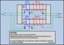
Usually dots shown on transformer windings indicate which end of a winding will cause flux to develop in the core in the same direction for every winding. My guess is that dots on the Spectra 11 schematic are being used to indicate the start(or end) of a particular winding not its relative flux polarity. Since the Spectra transformer uses UI-core with a primary on each leg wound in the same direction, if the primaries are to be wired in parallel the start of one primary must be connected together with the end of the other.
The attached pic shows how the primary and secondary windings are oriented and wired.
Attachments
Usually dots shown on transformer windings indicate which end of a winding will cause flux to develop in the core in the same direction for every winding. My guess is that dots on the Spectra 11 schematic are being used to indicate the start(or end) of a particular winding not its relative flux polarity. Since the Spectra transformer uses UI-core with a primary on each leg wound in the same direction, if the primaries are to be wired in parallel the start of one primary must be connected together with the end of the other.
The attached pic shows how the primary and secondary windings are oriented and wired.
Exactly, I know what You are saying.
But as they have illustrated it it will be a short circuit as they have interconnected both primary windings and also illustrated it together with a joint core. Regardless of the dots, the sum of the illustration will be wrong, I think.
Take the QUAD esl 63 or earlier Acoustats for an example, those schematics show it right.
Or am I just thick?
Perhaps it's the UI-core lineup that beats me...
- Home
- Loudspeakers
- Planars & Exotics
- Acoustat Answer Man is here