Massimo - here is another thought. The Spectra 4400 has a right and a left speaker. If they are backwards, high frequency dispersion will be wrong, possibly contributing to the lack of top-end you perceive. Imaging will also be negatively affected.
When set-up properly, each speaker should have the high frequencies coming from near the inner edge of each speaker. That is, highs will be coming from near the right edge of the left speaker, and left edge of the right speaker.
Your 2+2 speakers are identical - there is no left or right, and they can be used interchangeably.
Model X distortion woes…..
I have been busy and since I am not a tech, I am in the process of replacing almost every component on the board.
Here is a list of currently replaced components according to the parts list:
Caps:
C26,c35,c24,c32,c26,c37,c7,c8,c9,c10,c5,c6,c21,c15,c20,c33,c12,c13,c17,c18,c19 (swapped c1,,c2 with good amps because of cost)
Resistors:
R61,r43,r,44,r57,r58,r37,r32,r39,r53,r40,r54,r57,r58,r51
Semiconductors:
Q1,q2,q3,q4,q5,swapped op amp with known good), 5kv section main diodes
I am waiting for more parts mainly small caps.
Bottom line is, that I still have distortion elements that the “good amp doesn’t”
Yes, I have swapped tubes and every tube sounds good in the good amp. I have also swapped panels with the same results. Is it possible that one of the remaining few yet un-replace components could be causing the issue? My experience tells me that once all components are replaced that the issue should be fixed, but my fear is that the distortion, and slightly lower output issue will remain.
If anyone has any ideas, I would love to hear them! Thank you so much!
Greetings AcoustatAnswerMan and thanks for those instructions. Now I'm facing a follow-up problem that I need your help with. Quick background: I took out the two mk-131 interfaces from my 2MH speakers, brought them to a local tech to do the replacement of the degrading parts, and then brought the interfaces back home, resoldered the three leads to each panel, and powered them up... only to find a catastrophic mistake by the tech (long story short, after a lot of figuring out, the two input posts on one interface had been accidentally shorted to the metal panel and therefore to ground). Luckily, my amp reset itself and did not go up in smoke with that zero ohm load. I took the interface back to the tech who fixed his mistake. Now, to my great relief, both speakers work. However (and sorry for the long preamble), that one speaker which had had the input posts shorted together and to ground now has significantly louder output. To get a centered image with mono signal, I need to twist my balance knob all the way to 2:00 or 2:30 o'clock towards the other speaker. Now I'm trying to figure out what to examine next. I'm not an electronic technician, barely a somewhat educated newbie. And that tech is way over his head with electrostatic circuitry. He's helpful, but I need to give him clear instructions on what to look for.The speaker does retain a charge after being unplugged from AC power. The simplest way around this is to let the speaker sit for 24 hours after unplugging. Another quicker method, which may be difficult on the 2MH, is to unplug the speaker from AC, and then detach the red pin-plug from the interface and touch its tip to either the adjacent white or blue binding posts. Be sure not to touch any parts of the circuit while doing so.
Note that there was no significant level differences between L and R before the replacement of the degrading parts and the sidetrip down catastrophe-lane.
There are four things I am trying to find out:
- What would be the likely result of powering that interface while the two input posts are both shorted to gnd and therefore to each other?
- Why would that make the mistreated speaker louder than the other?
- What if I'm looking at the wrong suspect, and something is actually wrong with the other speaker's interface circuitry?
- Without specialized equipment, can I measure the bias voltage on both speakers as a first step in troubleshooting? I read somewhere something about "between 82 and 88 V DC on the bias output" but the circuit board is silkscreened with "5KV", which will instantly turn my Fluke into a pile of ashes. Is there a method for looking for that 82-88VDC anywhere on the circuit board as an indicator that the bias voltage on both interfaces is within acceptable tolerance?
As always, I am extremely grateful that you're there, and so generous with your knowledge and expertise.
Thanks in advance,
Daniel
P.S. There's no doubt the speakers have significantly different output levels. I did the usual trouble-shooting, using different input sources, swapping cables, everything. No matter what I throw at them, one speaker is louder.
Last edited:
Swap left and right channel - see if the other speaker now plays louder...
Maybe your amp left - right was connected wrong - and now has an issue on one channel...
Edit - looks like you did this...see the Slider resistor - make sure the two white wires off that slider resistor are reading same - if all the way wide (+2db), should read around 6ohm...
The voltmeter reading on Bias pin will depend on your probe impedance (10 meg ohm, etc)...mine was reading around your 80v, which was around 5kv...you can at least see if they are same on each interface...you should not damage your Fluke, as the current is very very low....
Last edited:
Already did that. There's no doubt about it, I tried swapping everything (sources, source cabling, speaker output cabling)... that one speaker is invariably louder than the other, not matter what.Swap left and right channel - see if the other speaker now plays louder...
Maybe your amp left - right was connected wrong - and now has an issue on one channel...
The subwoofer output on the MK131 interface is full range. The same is true of the MK-141 and Spectra interfaces. Woofer crossover is in the woofer box. Crossover frequency is around 150-200 HZ, not sure exactly. The MK-131 woofer crossover wasn't well-executed, so it might benefit from something improved.Also - AAM...can you let me know what the 1+1 with MK-131 interfaces (with outputs to Acoustat sub Woofer)...what is the crossover point to sub?
My (strong) suspicion is that the bias voltage on the less-loud speaker is out-of-spec. This is not an uncommon problem for speakers of that age. I suggest you measure the bias voltage on each speaker, and I'm sure you will find it is low on the less-loud speaker. I recommend replacing all five diodes and all five capacitors in the bias multiplier for both speakers. Instructions for measuring bias and replacing bias components have been posted numerous times on this thread. If you can't find them, I will post again (I don't have access to the documents where I am currently).Greetings AcoustatAnswerMan and thanks for those instructions. Now I'm facing a follow-up problem that I need your help with. Quick background: I took out the two mk-131 interfaces from my 2MH speakers, brought them to a local tech to do the replacement of the degrading parts, and then brought the interfaces back home, resoldered the three leads to each panel, and powered them up... only to find a catastrophic mistake by the tech (long story short, after a lot of figuring out, the two input posts on one interface had been accidentally shorted to the metal panel and therefore to ground). Luckily, my amp reset itself and did not go up in smoke with that zero ohm load. I took the interface back to the tech who fixed his mistake. Now, to my great relief, both speakers work. However (and sorry for the long preamble), that one speaker which had had the input posts shorted together and to ground now has significantly louder output. To get a centered image with mono signal, I need to twist my balance knob all the way to 2:00 or 2:30 o'clock towards the other speaker. Now I'm trying to figure out what to examine next. I'm not an electronic technician, barely a somewhat educated newbie. And that tech is way over his head with electrostatic circuitry. He's helpful, but I need to give him clear instructions on what to look for.
Note that there was no significant level differences between L and R before the replacement of the degrading parts and the sidetrip down catastrophe-lane.
There are four things I am trying to find out:
- What would be the likely result of powering that interface while the two input posts are both shorted to gnd and therefore to each other?
- Why would that make the mistreated speaker louder than the other?
- What if I'm looking at the wrong suspect, and something is actually wrong with the other speaker's interface circuitry?
- Without specialized equipment, can I measure the bias voltage on both speakers as a first step in troubleshooting? I read somewhere something about "between 82 and 88 V DC on the bias output" but the circuit board is silkscreened with "5KV", which will instantly turn my Fluke into a pile of ashes. Is there a method for looking for that 82-88VDC anywhere on the circuit board as an indicator that the bias voltage on both interfaces is within acceptable tolerance?
As always, I am extremely grateful that you're there, and so generous with your knowledge and expertise.
Thanks in advance,
Daniel
P.S. There's no doubt the speakers have significantly different output levels. I did the usual trouble-shooting, using different input sources, swapping cables, everything. No matter what I throw at them, one speaker is louder.
BTW, I doubt any damage was caused to the speaker by the shorted terminals. If your amp survived that, you should be okay. However, since your tech is not familiar with ESLs, I am curious what "degraded parts" were replaced, and with what. Photos might be helpful to determine that everything was done right.
Hello AAM...yes subwoofer speaker outs are full range, and the two crossovers are in the single Acoustat sub woofer box...and was "low pass" around 150 - 200hz...thanks for confirming
But the panels - they also were "high pass" at same 150-200hz, correct? The panels were obviously not full range (only had the single step up HF transformer, one resistor / capacitor Mixer network, etc)
But the panels - they also were "high pass" at same 150-200hz, correct? The panels were obviously not full range (only had the single step up HF transformer, one resistor / capacitor Mixer network, etc)
The instructions and parts list for replacement were provided by Roy Esposito, and the parts were ordered from Mouser, listed below:My (strong) suspicion is that the bias voltage on the less-loud speaker is out-of-spec. This is not an uncommon problem for speakers of that age. I suggest you measure the bias voltage on each speaker, and I'm sure you will find it is low on the less-loud speaker. I recommend replacing all five diodes and all five capacitors in the bias multiplier for both speakers. Instructions for measuring bias and replacing bias components have been posted numerous times on this thread. If you can't find them, I will post again (I don't have access to the documents where I am currently).
BTW, I doubt any damage was caused to the speaker by the shorted terminals. If your amp survived that, you should be okay. However, since your tech is not familiar with ESLs, I am curious what "degraded parts" were replaced, and with what. Photos might be helpful to determine that everything was done right.
Quantity Part #
10 583-R5000F-B R5000F-B 200mA 5000V 500ns
10 75-564R30GAD33 564R30GAD33 3300pF 3Kvolts 20%
2 588-SM104035006FE SM104035006FE 500M ohms 1%
2 647-UES1H221MHM UES1H221MHM 50volts 220uF 85c 16
4 576-0313003.MXP 0313003.MXP 250V 3A Slo-Blo
2 565-5018-0 5018-0 HEX HEAD BIND POST
2 565-5018-2 5018-2 HEX HEAD BIND POST
Since I wrote my plea for assistance, I checked the bias voltage on both interfaces (by measuring the DC voltage between the RED copper foil and the green ground copper foil on the circuit board, and powering up the interface). Oddly enough, the measured voltages are the same on both interfaces: 53.7 VDC, even though I expected a difference between them, to account for the different output volumes.
I wanted to check the output of the bias transformer, but my little voltmeter has a maximum input of 600 VAC, not high enough for the expected output of a healthy transformer at 750 VAC.
So I'm stumped, and with barely enough knowledge to be dangerous. Any guidance would be much appreciated.
Thanks again,
Daniel
It appears that the bias multiplier parts have already been replaced. Since you measured equal bias voltages, I think we can rule out any issues with the bias power supply. There's no need to measure the output of the bias transformer - if the HV outputs are equal, then bias transformers are okay as well.
So that leaves two possibilities: something is defective (or modified incorrectly) in the audio portion of one interface, or, something in the panels themselves are causing a bleed-down of the bias voltage in that speaker.
Have you swapped panels between the 2 interfaces? If the low output follows the panels, then you have a panel problem. If the low output follows the interface, then you have an interface problem. Report back and we'll go from there.
Trying to identify these two transformers purchased in 1984 and left in a box marked "Acoustat." Not sure how accurate that is or how proprietary they are. I'm attempting to liquidate a warehouse full of new/spare parts from the last 40 or so years so there's a lot of stuff mixed in. This one at least at the packing slip handwritten with the date. They look very similar to the ACOUSTAT TTA-117V x-formers but I can't be certain of this. A google search for the associated numbers doesn't produce many if any results. Any ideas? Pricing in 1984 for these was a whopping $190/ea. They fit the palm of the hand on sizing.
Attachments
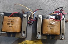
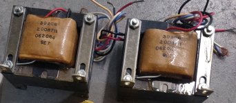
These are NOT TTA-117V, which is the bias transformer. It is the high-frequency audio step-up transformer from the MK-121 series of speaker interfaces, which spanned many years and models of Acoustat production. Unfortunately, they are not the much-improved Medallion version, but none-the-less of value to someone who needs one. Dollar value? Probably a couple hundred bucks to someone who needs one for repair, maybe less for the curious and/or experimental purposes. Interesting find.

Hey thanks for the quick reply! I appreciate the help. I think this is the second time you've been able to identify some Acoustat items with ease.
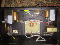
So being that I don't have a MK-121 in front of me, is it safe to assume that this image I lifted off google depicts the transformer(s) in question outlined in the red box?
So being that I don't have a MK-121 in front of me, is it safe to assume that this image I lifted off google depicts the transformer(s) in question outlined in the red box?
Attachments
Hi, I have a pair of 2+2 speakers and would like to add another pair of 2+2 speakers to create model 8’s. Is this possible?Stacking them that way will depend on total height achieved - is your ceiling high enough? I suppose you could do that for experimental purposes, and if you like the result, then build proper 8-panel frames. With 8 panels, I think you'd get the best results with the bottom panels essentially at floor level, as was done with all "stacked" Acoustat models. These models were 7-feet,10-inches tall, barely able to fit a standard 8-foot ceiling.
I would not recommend series-connecting the bias transformers. You may (and probably will) run into grounding issues, and the voltage may not divide evenly between the two transformers. Far better to use a 240/120V step-down transformer - it doesn't need to be very big (figure about 5 watts per speaker).
Yes, that is the high-frequency transformer circled in the photo. Note this is a very early version of the MK121, and that other versions existed in later years that were physically quite different but essentially the same electrically-speaking.Hey thanks for the quick reply! I appreciate the help. I think this is the second time you've been able to identify some Acoustat items with ease.
So being that I don't have a MK-121 in front of me, is it safe to assume that this image I lifted off google depicts the transformer(s) in question outlined in the red box?
- Home
- Loudspeakers
- Planars & Exotics
- Acoustat Answer Man is here