spectra 6 ????
Hi Andy thanks for responding .I'll try to be clearer,iwas hoping to build a six panel speaker with spectra panels and spectra interfaces from two spectra threes.i was going to set them to subwoofer so as reduce stress on the panels as an aid to longevity. Then experiment with subs to fill in the bottom end .I don't know what youd call them. My main question was the reason for using two amps because I thought they would be easier for the amp six panels wont drop as low and hence one amp would be more stable. I may have got this completely wrong but that's why I'm asking someone who knows what they are talking about. And in the UK were in lockdown again have to do something to pass the time...thanks in advance andy
Hi Andy thanks for responding .I'll try to be clearer,iwas hoping to build a six panel speaker with spectra panels and spectra interfaces from two spectra threes.i was going to set them to subwoofer so as reduce stress on the panels as an aid to longevity. Then experiment with subs to fill in the bottom end .I don't know what youd call them. My main question was the reason for using two amps because I thought they would be easier for the amp six panels wont drop as low and hence one amp would be more stable. I may have got this completely wrong but that's why I'm asking someone who knows what they are talking about. And in the UK were in lockdown again have to do something to pass the time...thanks in advance andy
If I understand correctly, your plan is to effectively stack two Spectra 3s, with the upper half driven by one interface, and the bottom half driven by a second interface. That arrangement would solve the problem of the differing values of the sector resistors, since each interface will be driving only 3 panels, as intended. You may find you have too much bass, but if using a subwoofer, perhaps you can compensate for that with careful choice of crossover point, slope, and levels. Experiment! Unless you have an especially robust amplifier, comfortable driving as low as 2 ohms, I would not recommend driving two interfaces in parallel from one amplifier channel. The interfaces are nominally rated at 4 ohms, although impedance varies considerably with frequency, and can dip lower than 4 ohms. For two interfaces in parallel, you'll be burdening your amp with a load of 2 ohms or less. Very few amps are up to that task.
Hi Andy sorry to be a pain, two stacked spectra 3s is exactly what I meant, but with regard to the amp mine has four sets of speaker out and I was thinking that running two sets of speaker cables might overcome that problem. Plus I won't need to drive the panels hard with subs taking part of the load?
My post number 1925 states all of the items I used on my 2+2's. Made a huge difference.
... Based on his advice, I went with Clarity CSAs as a reasonable price/performance ratio for the 47uF and 10uF and I'm very happy with them. I kept the stock 0.01uF caps though.
...
If your caps aren't electrolytic, they may be perfectly fine, although newer technology may yield an improvement...
Thanks to both of you for the advice on caps. Just what I was looking for.
Yes, the caps I had used are polypropylene, so not too worried about rushing to replace, but I do think newer could be an improvement. Key issue is the size of the 47uf cap. The 1+1 interface doesn't have room like the 2+2 appears to have. I will have to look up sizes of specific brands and make sure they will fit. The 47 I used years ago is a Solen. The Wonder Cap 10uf is about the same size. Undoubtely, a 47uf Wonder Cap would not have fit (if they were available that large). The Mundorf 47 looks huge in mraudioguru's photos! Will have to do bit of measuring.
i was going to set them to subwoofer so as reduce stress on the panels as an aid to longevity. . . . My main question was the reason for using two amps because I thought they would be easier for the amp six panels wont drop as low and hence one amp would be more stable.
with regard to the amp mine has four sets of speaker out and I was thinking that running two sets of speaker cables might overcome that problem. Plus I won't need to drive the panels hard with subs taking part of the load?
While you're thinking about the problem from a speaker standpoint (bigger panels and less bass to them, so you'll have less excursion), the issue is mostly related to the load presented to the amplifier (typically worst at high frequencies for an electrostatic speaker). In general, having more panels is a more challenging load for the amplifier because of increasing capacitance. This makes impedance lower at high frequencies.
Having two sets of outputs for bi-wiring doesn't help in the scenario you describe (driving two interfaces). Both ESL interfaces end up in parallel, which cuts the impedance in half compared to a single interface. A load that was already difficult (both low impedance and high in capacitive reactance) winds up twice as difficult. It's a tall order.
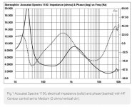
The following plot is not for your speaker, but it shows what a typical ESL load looks like. The combination of low impedance with large capacitive phase angle at higher frequencies is what some amplifiers have difficulty driving. From about 5 kHz and up, impedance is low. From 5 kHz to about 12 kHz, phase angle is also relatively high. While this impedance plot isn't as bad as some, if you cut the impedance in half by driving two interfaces in parallel, it winds up being a pretty tough load. The load in the bass region isn't super easy either, but at least the impedance is higher.
Acoustat Spectra 1100 loudspeaker Measurements | Stereophile.com
"Impedance-wise (fig.1), the Spectra 1100 offers no surprises. The sealed-box woofer is tuned to a low 27Hz. The HF contour switch was set to Medium for this graph; switching it to "High" drops the top-octave impedance to an amplifier-punishing 1.1 ohms at 20kHz. The upper bass impedance minimum is a still-demanding 3.6 ohms at 200Hz. Coupled with the low sensitivity, this implies that Spectra 1100 owners should avoid wimpy solid-state receivers, classy tube amplifiers, and the like."
Attachments
Last edited:
Not to quibble, but the vast majority of electrostatics sold these days are hybrids.
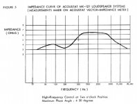
Acoustat impedance plot below is from the white paper "The Technology of Full-Range-Element Electrostatic Loudspeakers" by Strickland.
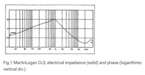
And here's a Martin Logan CLS plot. It's from an old review, so image quality is poor, and it's lacking phase data.
MartinLogan CLS loudspeaker 1987 Measurements | Stereophile.com
Looking at the amplifier load factor, the impedance curve (fig.1) is typically "electrostatic." Low at low frequencies, and with no visible signs of the 50Hz diaphragm resonance, it climbs steeply to a harmless 33 ohms by 1kHz. Above this level, the load is almost purely capacitive, falling with frequency at 6dB/octave, reaching 2.5 ohms at 10kHz, and finally bottoming out at a value of 1.6 ohms at 20kHz.
Acoustat impedance plot below is from the white paper "The Technology of Full-Range-Element Electrostatic Loudspeakers" by Strickland.
And here's a Martin Logan CLS plot. It's from an old review, so image quality is poor, and it's lacking phase data.
MartinLogan CLS loudspeaker 1987 Measurements | Stereophile.com
Looking at the amplifier load factor, the impedance curve (fig.1) is typically "electrostatic." Low at low frequencies, and with no visible signs of the 50Hz diaphragm resonance, it climbs steeply to a harmless 33 ohms by 1kHz. Above this level, the load is almost purely capacitive, falling with frequency at 6dB/octave, reaching 2.5 ohms at 10kHz, and finally bottoming out at a value of 1.6 ohms at 20kHz.
Attachments
I don't think definition of terms would qualify as "quibbling," especially when it's essential to the discussion as it is here. I would argue if there are non-electrostatic elements, it's no longer "an electrostat" just as it's not "a dynamic speaker" since each has unique impedance characteristics. That said, I find Strickland's graph possibly slightly optimistic, since it's unexpectedly (or ironically if it's to be accepted) better behaved than the hybrid's curve.
Last edited:
spectra 6 ????
Hi Andy ,mattstat,thank you for the advice I think it's soaking in. I have to the engineer who upgraded my amp he said the amp was designed to be able to drive apogee scintillas so should cope well. But he doesn't have the specs for the acoustats I'm building he suggested putting an inline resistor of 3 to 4 ohms to be on the safe side I'm sure I've come across this before but I can't find the right post that do you think?again thanks for the help
Hi Andy ,mattstat,thank you for the advice I think it's soaking in. I have to the engineer who upgraded my amp he said the amp was designed to be able to drive apogee scintillas so should cope well. But he doesn't have the specs for the acoustats I'm building he suggested putting an inline resistor of 3 to 4 ohms to be on the safe side I'm sure I've come across this before but I can't find the right post that do you think?again thanks for the help
The resistor will make the load more amplifier friendly. It's an easy way to run your experiment to see if you like the overall idea of stacking the speakers.
In general with an electrostatic load, adding a series resistor like this rolls off the very high frequencies. It's not a steep roll-off, so it's typically pretty benign. The exact frequency is interface/panel dependent.
In general with an electrostatic load, adding a series resistor like this rolls off the very high frequencies. It's not a steep roll-off, so it's typically pretty benign. The exact frequency is interface/panel dependent.
Acoustat 1+1 HR resistors question
This discussion has motivated me to ask about what I found in my 1+1 MK-121C interface: that we ended up with 3+15=18ohms of resistors in the high freq circuit, instead of the intended 16ohms. Since this was done >25years ago, I no longer have any idea how we ended up with that setup, though I recall we spent time playing with many pairs of resistors and doing listening tests. Any idea what effect this resistance difference would cause relative to the intended value?
This discussion has motivated me to ask about what I found in my 1+1 MK-121C interface: that we ended up with 3+15=18ohms of resistors in the high freq circuit, instead of the intended 16ohms. Since this was done >25years ago, I no longer have any idea how we ended up with that setup, though I recall we spent time playing with many pairs of resistors and doing listening tests. Any idea what effect this resistance difference would cause relative to the intended value?
Proper C-Mod Parts and so much confusion for me.
First,
I want to say thank you to everyone who answers questions in this thread and on this forum in general. It is rare now a days where someone can ask a question and get responses that actually make sense with little to no trolling. It is nice to see there are still places on the internet like this one. I am sure I am one of the people that ask the “dumb” questions.
I have posted on this thread several times and have had nothing but a great experience. I have gotten extremely busy at work and have wanted to post this question, and a few more pics of the insides of the interfaces. I just have not found the time to discharge the interfaces of power (I think unplugging from power over night will be long enough to discharge) and then take pictures.
Now onto my dilemma, I may just be overthinking this entire thing, but here goes.
I have Acoustat 3’s with the blue medallion updates already done. The interfaces are the mk121-2 interfaces. I would like to do the C-mod to my pair.
Now to my question(s)
#1. Is the mk121-2 interface the same as the mk121-2(a) interface? Or is it some other interface entirely? I have a few pictures of these speakers and the interface on post 2572 of this thread, if that is helpful to answer this question.
#2. Since I have the Blue Medallions already done on my mk121-2 interfaces, Do I need to follow different schematics and or pictures then what are provided in the Acoustat C-Mod rev 2018.pdf?
#3. Does anyone have a best parts to buy list to get the best sound/performance on the C-mod?
#4. If someone had a place to buy the correct parts for #3 above in the US, this would also be extremely helpful.
#5. Is there a consensus on what are the best parts / manufacturer to get for each item? Or does it just not matter? I have been trying to read up on the needed resisters, caps, and what else to buy to mount things properly inside the interface box. There is so much information on the internet about the C-Mod and C-Mod parts, but most of it seems years old.
To be honest, I am getting a bit overwhelmed. You would think it would be easy to just go buy the correct parts. It seems to be a lot of different types of caps/ resisters/manufactures. And a lot of opinions on which manufacturer is harsher sounding etc. So I am getting lost on what to buy and where to buy it in the US.
#6 Heck, I would buy a “Kit” that someone else worked up and had ready to purchase of the consensus “these are the parts u want for the best sound and reliability”. If anyone does this type of service, I think it would be helpful to others like me who get caught up in what part/manufacturer etc. I would be in line to make that purchase for this kind of service.
I am willing to do the work on installing the C-Mod, and any other mod that will make these speakers shine even more than they do now. I just need the correct parts to do it.
I swear I am not trying to be lazy and have someone else do the research or work involved. But I am guessing all this work has already been done. I just cannot find the “correct” list and schematics for my situation.
Why reinvent the wheel if you do not have to?
Again, if anyone can point me in the right direction, I would be very grateful.
Any help would be grateful.
Jesse
Any idea what effect this resistance difference would cause relative to the intended value?
I don't have a model of that exact interface, but simulating a similar circuit with transformer data I have on hand only shows about a 1 dB shift from the intended value to yours.
My guess from a distance is that you may have been using standard resistor values, and keeping things simplified to two resistors was more appealing and practical than getting precisely 16 ohms. Something like this is a typical compromise that's made when working on crossovers.
Last edited:
Thanks mattstat! You are probably right about why I have what I do. I am sure I was aiming for using just two resistors (in part because there is limited room and they aren't that small). Looking through the leftover resistors I have from back then (wow, still have!), I see only 12 ohms for other larger values, but then 4, 2.5, 2, 1.5, and 1 for smaller values. A number of these show evidence of solder, so they were definitely auditioned. In particular, I see the 2 and 2.5 were tried out, and yet I ended up using the 3's. Interesting. I would frankly prefer to boost the highs slightly for the current setup I am using (while Krells are being renewed), so I might get motivated to try the smaller values again (I believe that is what I need for HF increase).
The discussion of impedance drop at higher freqs reminded me of the time I used something like a 10kHz test tone on the Acoustats, and the Acoustat 120 amp I was using at the time blew it fuses almost instantly even though tones were not very loud. That is when I learned just what that drop meant to an amp.
The discussion of impedance drop at higher freqs reminded me of the time I used something like a 10kHz test tone on the Acoustats, and the Acoustat 120 amp I was using at the time blew it fuses almost instantly even though tones were not very loud. That is when I learned just what that drop meant to an amp.
The MK121 "C Mod" instructions were written (by me) to be general enough to cover all variations of the MK-121 series of interface. Electrically they are the same, although there are differences in layout and parts (particularly in the implementation of the HF balance control).
The instructions also list sources for parts. This list may be obsolete due to changes in what manufacturers/distributors are currently offering. The modifier is welcome to make changes in parts selection, as long as the basic values are used.
The instructions also list sources for parts. This list may be obsolete due to changes in what manufacturers/distributors are currently offering. The modifier is welcome to make changes in parts selection, as long as the basic values are used.
To followup on my own post...
Got the time to replace the 3ohms with 2ohms, so now have 2ohm-15ohm pairs (closer to the stock 16ohms total). This provided just about exactly the amount and type of HF boost I wanted. What I hear is boost to cymbals and not much else. Luckily, no upper midrange boost was apparent. So, it seems like the crossover frequency is quite high. Does anyone know?
I would frankly prefer to boost the highs slightly for the current setup I am using (while Krells are being renewed), so I might get motivated to try the smaller values again....
Got the time to replace the 3ohms with 2ohms, so now have 2ohm-15ohm pairs (closer to the stock 16ohms total). This provided just about exactly the amount and type of HF boost I wanted. What I hear is boost to cymbals and not much else. Luckily, no upper midrange boost was apparent. So, it seems like the crossover frequency is quite high. Does anyone know?
By changing the setting of the HF Balance Control, you are not really altering the crossover frequency as much as you are altering the high frequency peak in the equalization. That is why you hear a change only in the extreme high frequencies.
BTW, it's not really correct to think of a "crossover frequency" between low and high frequency transformers, as you might think of between a conventional woofer and tweeter. There is considerable overlap between the two transformers.
BTW, it's not really correct to think of a "crossover frequency" between low and high frequency transformers, as you might think of between a conventional woofer and tweeter. There is considerable overlap between the two transformers.
Thanks for info. Any idea where that peak is located? I was very pleased with the effect of increasing the HF balance, because it was just what I needed: boosting only the extreme highs. Since I did not recall what we had heard ~30 years ago when we "voiced" the system with fixed resistors, I had been reluctant to make changes because I was worried they would affect upper midrange too. Very pleased that I don't hear any effect there at all.
Of course it would be much easier to achieve desired balance if I had a variable resistor setup. Still considering whether I want to go that route, but I am not convinced it will sound as good. My recollection is that the fixed resistors were an improvement over the variable resistor with strap that came with my 1+1's. I actually found I still have those resistors--but not the straps--though I would switch to a pot if I went the variable route. I am still planning on replacing the 30 year old Wonder Caps with newer tech when I get a chance to study up on the huge range of available caps to figure out which can fit in the 1+1 interface (and which I want to pay for, multi-hundred dollar individual caps??).
Of course it would be much easier to achieve desired balance if I had a variable resistor setup. Still considering whether I want to go that route, but I am not convinced it will sound as good. My recollection is that the fixed resistors were an improvement over the variable resistor with strap that came with my 1+1's. I actually found I still have those resistors--but not the straps--though I would switch to a pot if I went the variable route. I am still planning on replacing the 30 year old Wonder Caps with newer tech when I get a chance to study up on the huge range of available caps to figure out which can fit in the 1+1 interface (and which I want to pay for, multi-hundred dollar individual caps??).
- Home
- Loudspeakers
- Planars & Exotics
- Acoustat Answer Man is here