Hi all, I have an immaculate Accuphase DP-65V Cd Player which does not work. It is a beauty of a CD player, built like a tank and in almost new condition. The mechanics are the same as the ones used in the Sony CDP 707ES. it has a magnetic sled moving the laser pickup and a very solid metal like CD tray.
The problem is that the tray opens and closes perfectly and very smooth. But once the CD is inside the motor does not spin and the sled with the laser pickup does not move.
Nothing happens. I replaced the complete laser with a good one (supposetly) but nothing improved. It looks like there is no power somewhere. I checked the power supply and there are three voltage regulators supplying two of them 8V and one 5V and the voltages are correct. The drive board has connectors with the voltages marked. One is supposed to input 7V but does 8.64V instead. Since no Accuphase manual is available i am trying to use the Sony CDP 707 schematics but am lost at this point. Any help available to try to fix this player before dumping it? What should I check?
It must move the lens three times when you power up or the shelf get in. In CDP-779es or similars, the laser pickup makes a movement from the inner to the outside and again to the center when you power up the cd player, and then the three times lens movement. It could be interesting you be able to see RF signal, though it were only a slight movement when the cd tries to read.
Mira si la lente se mueve tres veces cuando enciendes o se mete la bandeja. En los sony como el cdp-779 cuando lo enciendes el laser se va al exterior y luego vuelve al centro, y luego intenta leer el cd moviendo tres veces la lente. Sería interesante que pudieras ver la señal RF con un osciloscopio, aunque sea tan solo el intento de lectura, o lo que fuere.
Mira si la lente se mueve tres veces cuando enciendes o se mete la bandeja. En los sony como el cdp-779 cuando lo enciendes el laser se va al exterior y luego vuelve al centro, y luego intenta leer el cd moviendo tres veces la lente. Sería interesante que pudieras ver la señal RF con un osciloscopio, aunque sea tan solo el intento de lectura, o lo que fuere.
Hola Manolo, el problema es que el cabezal no hace ningun movimiento sobre el carril y se puede mover a mano,sin que se note ninguna resistencia. Cuando al gaveta entra y se coloca en el recorrido final el conjunto cabezal/motor sube por el sistema de leva que lo empuja hacia arriba no observo ningun movimiento del cabezal laser ni de la lente del laser y el motor no gira.
Tengo varios manuales de Accuphase y ninguno tiene esta unidad de transporte.
Hello Manolo, the problem is that the head makes no movement along the rail and it can be moved by hand without noticing resistance. As the drawer is retracted and placed on final travel, the head/motor assembly is raised due to the cam system pushing it up, but I see no movement of the laser head or lens and the motor does not rotate . I have several Accuphase manuals and none of them have this transport unit.
There are not much pictures in the net of this cd player.
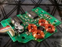
The part suspect is this:
https://www.gzhifi.com/ls/images/202303/1679364080592600173.jpeg
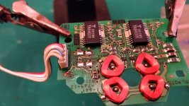
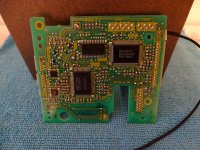
As you can see the there are four integrated circuits with heat sink:
It should be one for focus coil, one for tracking coil, one for laser movement in the rail, and another for to open/close the shelf.
But as you can see, there is another printed card below this.
So, check this card and follow focus, tracking, laser ICs signals,
Check power supply of this zone, that is not visible in the google pictures.
Este equipo no lo conozco, y no hay muchas imágenes en internet.
La parte sospechosa es la foto cuyo enlace está arriba.
Puedes ver cuatro circuitos integrados, supuestamente(e insisto, son suposiciones) uno debería ser para la bobina del foco, otro para bobina de tracking o seguimiento, otro para mover el laser a través del rail, y otro para hacer entrar o salir la bandeja.
Se puede entrever que debajo hay otra tarjeta que puede que tenga relación con el fallo.
También estaría bien que localices la fuente de alimentación de esta zona y revisar si falta alguna tensión, revisar los reguladores de tensión de 5V, -5, etc...
The part suspect is this:
https://www.gzhifi.com/ls/images/202303/1679364080592600173.jpeg
As you can see the there are four integrated circuits with heat sink:
It should be one for focus coil, one for tracking coil, one for laser movement in the rail, and another for to open/close the shelf.
But as you can see, there is another printed card below this.
So, check this card and follow focus, tracking, laser ICs signals,
Check power supply of this zone, that is not visible in the google pictures.
Este equipo no lo conozco, y no hay muchas imágenes en internet.
La parte sospechosa es la foto cuyo enlace está arriba.
Puedes ver cuatro circuitos integrados, supuestamente(e insisto, son suposiciones) uno debería ser para la bobina del foco, otro para bobina de tracking o seguimiento, otro para mover el laser a través del rail, y otro para hacer entrar o salir la bandeja.
Se puede entrever que debajo hay otra tarjeta que puede que tenga relación con el fallo.
También estaría bien que localices la fuente de alimentación de esta zona y revisar si falta alguna tensión, revisar los reguladores de tensión de 5V, -5, etc...
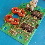
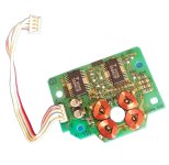
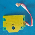
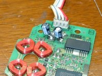
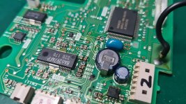
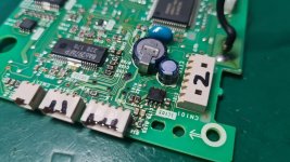
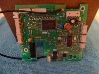
Here is a picture of the Driver board. There is no other board below, the two flat cables at the front go to the front panel and the rear one to an option board to plug in optional input and output boards, which are empty. The integrated circuits for Tracking Drive, Focus Drive and Tray are Dual Power Operational Amplifiers Toshiba TA7256P. The Sled Drive has also TA7256P and a C4570HA a ,The spindle Drive has a NJM4556LD dual operational amplifier.


Perhaps the DP-67 and 77 are similar:
https://elektrotanya.com/showresult?what=Accuphase+dp&kategoria=Minden&kat2=Minden
https://elektrotanya.com/showresult?what=Accuphase+dp&kategoria=Minden&kat2=Minden
AccordingHi all, I have an immaculate Accuphase DP-65V Cd Player which does not work. It is a beauty of a CD player, built like a tank and in almost new condition. The mechanics are the same as the ones used in the Sony CDP 707ES. it has a magnetic sled moving the laser pickup and a very solid metal like CD tray.
The problem is that the tray opens and closes perfectly and very smooth. But once the CD is inside the motor does not spin and the sled with the laser pickup does not move.
Nothing happens. I replaced the complete laser with a good one (supposetly) but nothing improved. It looks like there is no power somewhere. I checked the power supply and there are three voltage regulators supplying two of them 8V and one 5V and the voltages are correct. The drive board has connectors with the voltages marked. One is supposed to input 7V but does 8.64V instead. Since no Accuphase manual is available i am trying to use the Sony CDP 707 schematics but am lost at this point. Any help available to try to fix this player before dumping it? What should I check?
http://www.myav.com.tw/market/printthread.php?s=8b0ab8e678ee34a0223c02116bfac5b5&threadid=20488094
the laser head is the KSS-272A.
Sony's CDP707ES don't use the same mechanism/loader, because the laser unit is here the KSS-190A Maybe you mean the CDP-X707ES.
According vasiltech.ru the Accuphase models DP-65(V), DP-75(V) and Transport DP-90 so as the SONY models CDP-333ESJ, CDP-555ESA, CDP-555ESJ, CDP-777ESA, CDP-777ESJ, CDP-X303ES, CDP-X339ES, CDP-X505ES, CDP-X559ES, CDP-X707ES and CDP-X779ES have the laser unit "KSS-272A" in use.
Check out the diyaudio threads concerning KSS-272A and also the threads regarded the mentioned SONY cd player models.
The main deficiency in this laser unit is the used laser diode SLD-104 and the plastic suspension of the lens due to the short life expectancy.
That's the reason why this laser unit none have been available for a long time and only a remaining stock appears from time to time for a very high asking price.
Therefore some guys have find out the right steps for a refurbishing procedure of this and other laser units from SONY's KSS-Series - e.g. here:
https://www.diyaudio.com/community/threads/kss-272a-dont-blame-the-laser-diode-its-the-lens.385706/
BTW - If Accuphase had chosen JVC (Optima Series), most CD devices would still be running today.
https://www.diyaudio.com/community/...ct-1-ct1-better-than-vam1254-cdpro2lf.149032/
Another deficiency are leaked SMD electrolytic caps on the motor control PCB for the brushless disc resp. turntable motor (please note: this issue is widespread on SONY, including the ES series).
The motor control PCB is a part of the whole mechanism - go to the attachments.
If you buy this unit as replacement part - e. g. under
https://www.ebay.com.my/itm/225616866931
replace both SMD electrolytics against high quality versions before you replace the whole unit.
If leaked material have cause oxidation on the traces try this methody:
Attachments
-
 SONY CDP-559ES motor control-II.jpg295.7 KB · Views: 24
 -
 SONY CDP-559ES motor control.jpg172.7 KB · Views: 23
 -
 SONY CDP-559ES motor control-III.jpg275.4 KB · Views: 24
 -
 660090-7535c1fc9466cbdeebe5169eee734082.jpg10.1 KB · Views: 19
 -
 660106-729e8b0168e1111d075063f2249f0746.jpg11 KB · Views: 17
 -
 IMG_20181021_004020_S.jpg181.1 KB · Views: 21
 -
 P-20211024-182312-v-HDR-Auto.jpg352.9 KB · Views: 28
 -
 CDP-X559ES new caps.jpg237.9 KB · Views: 23
 -
 KSS-272A Servobord.jpg261.3 KB · Views: 24
Last edited:
Yes, KSS-272A is in CDP-X707ES. The "X" is important.
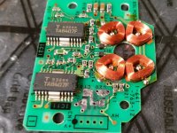
I don't know if this Accuphase have these spindle motor driver, but I've seen this circuit working with these capacitors totally dried. This capacitors are for power line filter, are not importants.
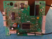
I don't know if this Accuphase have these spindle motor driver, but I've seen this circuit working with these capacitors totally dried. This capacitors are for power line filter, are not importants. The other circuit, the digital procesor, I think Accuphase is different circuit, own design. But this Sony digital procesor card, the 100uf 6,3V are not important, but this capacitor should be replaced due it is prone to leakage, and corrode the printed circuit. And the backup battery is prone to get oxid, I always remove it, I don't place any new. It does not worth.
I don't know if this Accuphase have these spindle motor driver, but I've seen this circuit working with these capacitors totally dried. This capacitors are for power line filter, are not importants.
I don't know if this Accuphase have these spindle motor driver, but I've seen this circuit working with these capacitors totally dried. This capacitors are for power line filter, are not importants. The other circuit, the digital procesor, I think Accuphase is different circuit, own design. But this Sony digital procesor card, the 100uf 6,3V are not important, but this capacitor should be replaced due it is prone to leakage, and corrode the printed circuit. And the backup battery is prone to get oxid, I always remove it, I don't place any new. It does not worth.
According the images under
https://www.hifi-workshop.com/?p=736
the Accuphase Transport model DP90 don't use an own board for the spindle motor drive unit (only an own servo board for tracking, focus and PCM decoding).
And I would be surprised if Accuphase had its own spindle motor control on the other models DP65/75(V).
In retrospect, it's simply shocking to me that such inferior parts are surrounded by otherwise very high-quality parts.
What actually does Accuphase say to the customers In the event of a necessary laser unit replace resp. repair to eliminate the non-reading of the TOC after tray-closing ?
Actually, Accuphase should develop a general solution to eliminate all weak points, even if the cd player devices are 30 years old and partly older.
This could be achieved with JVC parts from the Optima series, as these were replacement parts and could only rarely be replaced due to their high reliability and are therefore still available in large numbers as NOS goods.
Last edited:
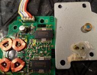
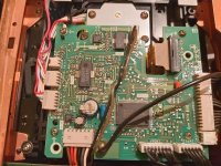
the CD mechanism of the DP65V is identical to the one installed in the DP90. I checked the spindle motor separating the metal plate and the two suspected Elkos are intact and measure correct capacity. All Voltages are correct, except ones marked 7 V on the logic board which are actually 8.6V. I suspect a printing error, since the power supply from Trafo to bridge rectifier and on to the Elkos has no faults in its components
Since I have no schematic for the DP665V there is not much I can do. An oscilloscope might help , but with no schematic its impossible to start measuring.
What is the sequence that occurs when a CD is inserted into the drawer and it is drawn into the reader? Should the reading head move first or the spindle motor start spinning first? On this DP65V nothing moves when the CD is drawn into the player.
maybe the service manual of SONY's CDP-X559ES helps a bit.
The SMD caps on motor control board are to be replaced, because by measuring it isn't possible without de-solder to determine the internal resistance.
Both 10uF caps goes from VCC/2 (actually U-ref) to +7V and GND. Best solution is replace by WIMA MKS 2u2 in smallest size.
Power supply version on Accuphase seems to be different but the +7VDC on logic board (servo board) must actually also come (like on SONY's CDP-X559ES) from an integrated (or maybe discrete) voltage regulator.
Attachments
SONY's Servo-PCB "1-641-810-21" / "1-641-810-12"
under the keyword "1-641-810" (SONY order code for Servo PCB, e. g. 1-641-810-21 or 1-641-810-12) I have found a lot of URL's - e. g.
http://www.hifimuseum.de/sony-cdp-557-esd.html
https://vintage-audio-laser.com/A-l-atelier-page-69
https://www.elektroda.pl/rtvforum/topic3697813.html
https://www.ebay.de/itm/276251889813
https://www.ebay.de/itm/256403582729
https://www.circuitsonline.net/forum/view/126680
https://www.diyaudio.com/community/threads/cdp-x779es-dig-psu-repair-or-not.311205/
https://www.diyaudio.com/community/threads/sony-cdp-x339es-cd-player-problems.287043/
https://zelfbouwaudio.nl/forum/viewtopic.php?t=27899
http://www.ks19561005.sakura.ne.jp/9999/ServiceManual/Sony,CDP-X505ES_service.pdf
according some descriptions main issue is unwanted corrosion on traces and thus interrupts at the plated-through holes in the areas of elcaps.
E. g. in the holes for pins of C302 (100.000uF/5,5V - go to the attached files) connected on PIN28 of IC302 (S-RAM LH5160TA) and in the holes for pins of C110 (100uF/6V3) so as additional holes in the area of this elcaps.
If this parts already replaced and all interrupts remove without success, it is the best way to replace the whole servo PCB by a version with correct operation (removed from another CD player as a test).
Despite the small size of this servo board, the degree of complexity is very high because many components are soldered on both sides.
Unfortunately, I cannot say how likely the failure rate of the other SMD chip capacitors and chip resistors as well as the QFP chips is.
P.S.: C302 must actually be a memory cap.
In a FM stereo tuner with memory for various radio stations such caps often in use. If loss of memory occurs in FM tuner due empty memory battery or defective super cap a new station seek/storage procedure must be started after replace battery or super gold cap.
What actually is to do after loss the memory on this servo board ?
under the keyword "1-641-810" (SONY order code for Servo PCB, e. g. 1-641-810-21 or 1-641-810-12) I have found a lot of URL's - e. g.
http://www.hifimuseum.de/sony-cdp-557-esd.html
https://vintage-audio-laser.com/A-l-atelier-page-69
https://www.elektroda.pl/rtvforum/topic3697813.html
https://www.ebay.de/itm/256403582729
https://www.circuitsonline.net/forum/view/126680
https://www.diyaudio.com/community/threads/cdp-x779es-dig-psu-repair-or-not.311205/
https://www.diyaudio.com/community/threads/sony-cdp-x339es-cd-player-problems.287043/
https://zelfbouwaudio.nl/forum/viewtopic.php?t=27899
http://www.ks19561005.sakura.ne.jp/9999/ServiceManual/Sony,CDP-X505ES_service.pdf
according some descriptions main issue is unwanted corrosion on traces and thus interrupts at the plated-through holes in the areas of elcaps.
E. g. in the holes for pins of C302 (100.000uF/5,5V - go to the attached files) connected on PIN28 of IC302 (S-RAM LH5160TA) and in the holes for pins of C110 (100uF/6V3) so as additional holes in the area of this elcaps.
If this parts already replaced and all interrupts remove without success, it is the best way to replace the whole servo PCB by a version with correct operation (removed from another CD player as a test).
Despite the small size of this servo board, the degree of complexity is very high because many components are soldered on both sides.
Unfortunately, I cannot say how likely the failure rate of the other SMD chip capacitors and chip resistors as well as the QFP chips is.
P.S.: C302 must actually be a memory cap.
In a FM stereo tuner with memory for various radio stations such caps often in use. If loss of memory occurs in FM tuner due empty memory battery or defective super cap a new station seek/storage procedure must be started after replace battery or super gold cap.
What actually is to do after loss the memory on this servo board ?
Attachments
-
 Sony Servo-PCB 1-641-810-12-0,1F-5V5-II.jpg77.2 KB · Views: 13
 -
 Sony Servo-PCB 1-641-810-12-0,1F-5V5-I.jpg40.5 KB · Views: 14
 -
 Sony Servo-PCB 1-641-810-12-0,1F-5V5-III.jpg64.3 KB · Views: 13
 -
 Sony Servo-PCB 1-641-810-12-I.jpg476.7 KB · Views: 14
 -
 Sony Servo-PCB 1-641-810-12-II.jpg459.6 KB · Views: 11
 -
 Sony Servo-PCB 1-641-810-12-III.jpg442.1 KB · Views: 12
 -
 Sony Servo-PCB 1-641-810-12-III.jpg442.1 KB · Views: 14
 -
 IMG_20181020_224603_S.jpg222.6 KB · Views: 15
 -
 IMG_20181021_004020_S.jpg181.1 KB · Views: 11
Last edited:
The spindle motor won't have anything to do with initializing cycle. First the magnetic sled motor has to move the head and laser has to detect the disc for the spindle motor to engage. I have esoteric transport with the same problem area. The head moves half way on magnetic tray and the laser tries to focus outside the disc perimeter. When I move the head by hand under the disc clamp the player reads TOC and plays without the problem. Its a major pita to disassemble the transport to gain access to a servo board and check point and I don't have schematic as well so I'm waiting for a proper mood to dig into it.
Did you check all the micro-switches which are there?
Did you check all the micro-switches which are there?
- Home
- Source & Line
- Digital Source
- Accuphase DP-65V dead transport section