Yes, see post 51.Here a picture with the caps
I very much doubt that replacing the transistors alone brought somehow hum. Any chance the different pinout caused issues?
I know that there is a different pinout between these transistors, but I verified again, I've made the correct pinout with the BC's transistors.
Thank you for your reply! Yes, of course I already read this whole thread including post 1 and read it again just yet. But it's still not clear for me whether you found something for the P-300L. What am I missing? You say you were looking for a schematic, but that your problem (with the unit or with the search?) is solved. It being solved can be because you found what you were looking for or that you didn't need it anymore ")
I listed available schematic copies that I own of this company in post 1.
The original problem on Accuphase P-300L was solved without diagram.
A first post can be edited any time, so I included new schematic entries.
It may be possible to find more diagrams at Elektrotanya or HiFi Engine.
Now this thread is for schematic and repair experience exchange.
The original problem on Accuphase P-300L was solved without diagram.
A first post can be edited any time, so I included new schematic entries.
It may be possible to find more diagrams at Elektrotanya or HiFi Engine.
Now this thread is for schematic and repair experience exchange.
All right, now the information is complete. Your problem was solved by solving the problem without schematic.
What I do have on the P-300L, is this schematic made by guy in a YouTube clip about repairing a P-300L. He drew the schematic himself based on a P-500 schematic and tailored it by looking at the amp boards of the P-300L. But is has a disclaimer that it may contain faults.
But it is missing the other parts than the amp boards. But maybe it is helpful to someone.
Credits to Vintage Audio Fan: https://www.youtube.com/@VintageAudioFan
Wow, this is just amazing. All of a sudden someone uploaded the Servical Manual + Schematic of the P-300L on Hifi Engine. Really a high quality scan.
Be aware: it is for units with serial number F4Y001. Mine happens to be J5W***
Please add it to the first post.
Be aware: it is for units with serial number F4Y001. Mine happens to be J5W***
Please add it to the first post.
Attachments
I don't understand, why service manuals and schematics from certainly models of this brand are easy to find and from certainly other models very hard or not to find. What could be the reason therefore ?
BTW - the often assumed or given reason by the manufacturer (protection of intellectual property or the prevention of cloning for commercial purposes) why the circuit diagrams are not published does not correspond to the real reason in my opinion.
The real reason is that a company would be very embarrassed if it had to admit that all versions (revisions) were not completely documented, and this would often make subsequent repair services considerably more difficult.
I had often wasted a lot of time during troubleshooting due to misprints in the circuit diagram that I had not initially expected.
Seen in this way, own creating of the circuit diagram is actually sometimes an advantage.
P.S.: For P300 variations check out this URLs:
https://www.diyaudio.com/community/...00x-not-p-300-p-300s-schematic-wanted.350149/
https://www.diyaudio.com/community/threads/accuphase-p-300s.340058/#post6095754
Last edited:
this is the owner's (instruction) manual.ACCUPHASE C222 Service Manual free download, schematics, eeprom, repair info for electronics
Scroll below the picture and wait for "Get Manual".
under
https://www.accuphase.com/cat/c-222en.pdf
is to find on page 2 a simplified schematic without values and without mode select switches - but helpful for understand the theory of operation and maybe helpful for create the schematic diagram in detail with help of the associated boards - removed from the preamp device.
@tiefbassuebertr C-222 schematic attached.
Attachments
Nope, this one I already found on Hifi engine: https://www.hifiengine.com/manual_library/accuphase/c-222.shtml
I also have the P-300L schematic and SM, already added to this thread.
I am desperately looking for a C-200L schematic and even better a SM. But it seems to me those are non-existent.
I also have the P-300L schematic and SM, already added to this thread.
I am desperately looking for a C-200L schematic and even better a SM. But it seems to me those are non-existent.
I recently bought one from Japan (100V unit) and I'm planning on overhauling it to make it future proof. It is working for now, but it's completely original. I want to replace all electrolytics, diodes (except the light emitting LT-8001P ones), zener diodes, DC balance pots, the switching relays and maybe a few fusible resistors. Just to make sure it keeps on playing for another 20+ years.
Normally I use the schematic for component identification and the SM for adjustment procedures. Recently I did a similar overhaul of a C-222 and with the schematic I was able to figure out where to measure for DC offset during the adjustment of the various DC offset pots (4 per channel).
It may be possible to figure it out without schematic, but far from ideal.
Btw, I also discovered a database on the Japanese Accuphase website where they have all instruction/owner manuals available, but they are all in Japanese. It may be of help for some. Check it here
Sometimes it is the case, that with the same model name exist only with an additional identifier, number or letter (e.g. MK-II, AE for "advance edition" etc.).I recently bought one from Japan (100V unit) and I'm planning on overhauling it to make it future proof. It is working for now, but it's completely original. I want to replace all electrolytics, diodes (except the light emitting LT-8001P ones), zener diodes, DC balance pots, the switching relays and maybe a few fusible resistors. Just to make sure it keeps on playing for another 20+ years.
Normally I use the schematic for component identification and the SM for adjustment procedures. Recently I did a similar overhaul of a C-222 and with the schematic I was able to figure out where to measure for DC offset during the adjustment of the various DC offset pots (4 per channel).
It may be possible to figure it out without schematic, but far from ideal.
In some cases the differences to that basic model without this "SUFFIX" are very low, so that no new circuit diagram was drawn.
Instead this only a supplementary paper was created, in which the differences to the basic model are described.
Maybe that's the case even here. Former Accuphase repair service technicians should actually know this.
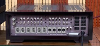
With the C-200 series and all the later suffixes (S, X, L and V), that is not the case unfortunately. There is 5 years between every newer version and when I look at the schematic of the C-200X from 1980 (the one before the C-200L from 1984), it looks completely different. For instance the X has boards of left and right channels combined, while the C-200L has separate boards per amplifier stage and per channel. And the X has only a few miniature relays, while the L is stuffed with miniature relays (around 20 to 25 pieces).
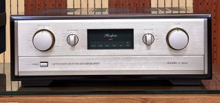
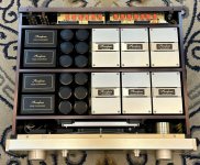
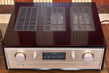
I think the C-200L has more in common with the the C-280 as far as I can see. But still, they're not equal.
C-280:

C-200L:

The main difference is that the C-280 has separate power supplies for both channels, whereas the C-200L has a shared power supply for both channels. I think it's fair to say the the C-200L is a poor man's C-280.
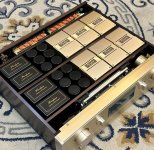
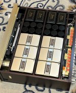
I reported earlier that the unit was working fine, but it has some troubles:
The Alps rotary switch for Stereo/Rev stereo/Mono switching before:

Both channels restored:

I think I will open a thread myself for this C-200L restoration...
I think the C-200L has more in common with the the C-280 as far as I can see. But still, they're not equal.
C-280:
C-200L:
The main difference is that the C-280 has separate power supplies for both channels, whereas the C-200L has a shared power supply for both channels. I think it's fair to say the the C-200L is a poor man's C-280.
I reported earlier that the unit was working fine, but it has some troubles:
- One channel cutted out regularly. I've solved this by taking apart the Stereo/Mono selector switch (who even needs that switch?) and I restored the contacts of the switch. It is a classic Alps rotary switch which all suffer the same problem of oxidation. I restored a few of those in my life. It was really dissapointing to see the the engineers placed relays everywhere for signal switching, but the audio signal goes through a simple switch for this function.
- The right channel has lesser output. I have to set the balance pot to 3 o'clock to have equal volumes left and right.
- It runs pretty warm/hot, but the may be normal due to it operating in Class A.
- The subsonic switch creates a gnarly hiss/crackle over my tweeters when pushed on and off.
The Alps rotary switch for Stereo/Rev stereo/Mono switching before:
Both channels restored:
I think I will open a thread myself for this C-200L restoration...
Accuphase C - 280V
https://audiocircuit.dk/downloads/accuphase/Accuphase-C280V-pre-sm.pdf


Balanced Line Driver with Floating Output
https://sound-au.com/balance.htm
https://audiocircuit.dk/aphex/
https://audiocircuit.dk/downloads/aphex/Aphex-2020FMPro-ba-sch.pdf
https://audiocircuit.dk/downloads/aphex/Aphex-2020FMPro-ba-sm.pdf
https://audiocircuit.dk/downloads/aphex/Aphex-Dominator_ll-pl-sch.pdf
https://audiocircuit.dk/downloads/aphex/Aphex-Dominator_ll-pl-sm.pdf
https://www.fmacoustics.com/company/heritage/fm-214-fm-216/
http://www.gyraf.dk/schematics/schematics.html
http://www.gyraf.dk/schematics/Neotek_Elite_Bal_Outputs.GIF
http://www.gyraf.dk/schematics/schematics.html
http://audiocircuit.dk/downloads/yamaha/Yamaha-PM1800-mix-sm.pdf
https://elektrotanya.com/ssl_sl4000g_console_sm.pdf/download.html
https://elektrotanya.com/studer_d732_sm.pdf/download.html
https://audiocircuit.dk/downloads/accuphase/Accuphase-C280V-pre-sm.pdf
Balanced Line Driver with Floating Output
https://sound-au.com/balance.htm
https://audiocircuit.dk/aphex/
https://audiocircuit.dk/downloads/aphex/Aphex-2020FMPro-ba-sch.pdf
https://audiocircuit.dk/downloads/aphex/Aphex-2020FMPro-ba-sm.pdf
https://audiocircuit.dk/downloads/aphex/Aphex-Dominator_ll-pl-sch.pdf
https://audiocircuit.dk/downloads/aphex/Aphex-Dominator_ll-pl-sm.pdf
https://www.fmacoustics.com/company/heritage/fm-214-fm-216/
http://www.gyraf.dk/schematics/schematics.html
http://www.gyraf.dk/schematics/Neotek_Elite_Bal_Outputs.GIF
http://www.gyraf.dk/schematics/schematics.html
http://audiocircuit.dk/downloads/yamaha/Yamaha-PM1800-mix-sm.pdf
https://elektrotanya.com/ssl_sl4000g_console_sm.pdf/download.html
https://elektrotanya.com/studer_d732_sm.pdf/download.html
Attachments
-
 1713628686472.jpg350 KB · Views: 23
 -
 1713628689997.jpg734.5 KB · Views: 17
 -
 1713628688552.jpg529.7 KB · Views: 18
 -
 1713628689273.jpg395.8 KB · Views: 19
 -
 1713628690788.jpg1,009 KB · Views: 17
 -
 1713628692154.jpg413.8 KB · Views: 22
 -
Accuphase-C-250-Brochure.pdf2.3 MB · Views: 21
-
Accuphase-C-260-Brochure.pdf3.5 MB · Views: 17
-
Accuphase-C-270-V-Brochure.pdf3.6 MB · Views: 23
-
Accuphase-C-275-V-Brochure.pdf375.7 KB · Views: 14
-
Accuphase-C-280-V-Brochure.pdf4 MB · Views: 19
-
Accuphase-C280V-pre-sm.pdf2.6 MB · Views: 14
-
Accuphase-F-20-Brochure.pdf2 MB · Views: 15
-
Accuphase-F-25-Brochure.pdf2.3 MB · Views: 18
- Home
- Amplifiers
- Solid State
- Accuphase C-280, E-303X, P-266, P-300L, P-500 and others diagrams, repair etc