Yes, but as Scott noted earlier, sound rolls off at 6 dB for every doubling of distance, so it's a 4x power drop from 1-2 m and again from 2-4 m, etc. and why multiple efficient drivers [horn loaded or not] are required in prosound apps to hit the hearing impairing loud dB/m required to pump 120 dB out these long distances from the sound 'wall'.
GM
GM
Using the method to adjust TABAQ to different speaker.
XRK,
Tried to use the method to adjust the dimensions for a TABAQ with our favorite 3" driver, the Vifa TC9FD-18-08.
Need clarification. When you say to adjust the length of the chamber to 30 to 40 inches, do you try to maintain the same volume of the chamber that WinISD concocted? or Do you refigure the volume with the same width and depth measurements and maintain the CSA only?
Thanks for the help.
JHutka
Jhutka,
I use WinISD as a starting point for the volume and vent dimensions. For low Qts drivers, I will often have to increase the volume substantially in order to get sufficient bass extension. However, for the TC9FD, it is a high Qts driver so the volume WinISD gives you is pretty good. Once you set a reasonable length, like say, 40 in or 45 in, calculate the main TL CSA required to get the same volume as predicted by WinISD. Use the same vent CSA and length that WinISD gives you, or you can try to tune it a little higher and the MLTL effect will actually "pull it" lower. I got a request to design a quad driver bipole MLTL for the TC9FD, I will post the design soon.
Regards,
X
AMLTL Design for Quad Bipole with TC9FD
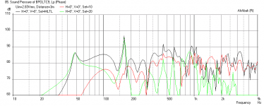
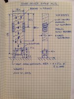
I got a request to design a quad driver bipole MLTL with the Vifa TC9FD. Using WinISD, I get a box volume of 67 liters and for a rectangular vent with dimensions of 4 in x 7 in, the length was 6 in (WinISD chose a 55 Hz tuning freq). So I assume a length of 45 inches and baffle width of 7 inches, this sets the depth at 13 inches. According to my AMLTL design rule: the drivers are assumed to be mounted at 1/3 distance from closed end (15 in) and use about 0.5 lb/cu ft of polyfill stuffing in upper 2/3rds of line. The vent is a rectangle that is down firing and the speaker sits on 5 in tall legs. Drivers are wired parallel (upper front & back parallel, lower front & back parallel) and in series upper and lower to get total 8 ohms.
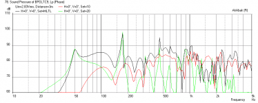
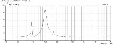
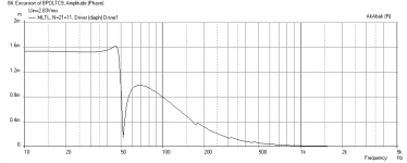
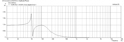
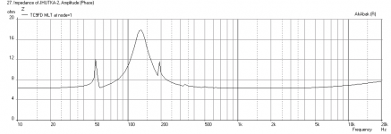
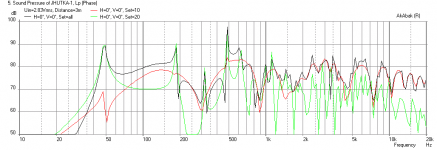
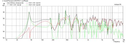
Below is the simulation in AkAbak with these dimensions. The simulation is with the speaker 60 in from a back wall, 1 watt input, measurement at 3 meters away. I then reduced the vent length to 5 inches to boost the bass output a bit and to bring the peak to about 50 Hz rather than sub 50 Hz. The fs is 120 Hz so you don't want to go too much lower than what WinISD predicts. The second plot is the simulation with the shortened 5 in vent and the third plot is the impedance, and fourth plot shows cone displacement (well controlled).
As you can see, if I had done nothing to the dimensions from WinISD, it still would work pretty well. Just ignore all the sharp peaks and dips - they will smooth out with stuffing which AkAbak cannot model.
So the final design is up to you whether you want the 6 in or 5 in long vent. The output of circa 85 dB at 3 meters away with 1 watt is not bad for $48 worth of drivers in a bipole configuration where you do not have any baffle step loss.
I got a request to design a quad driver bipole MLTL with the Vifa TC9FD. Using WinISD, I get a box volume of 67 liters and for a rectangular vent with dimensions of 4 in x 7 in, the length was 6 in (WinISD chose a 55 Hz tuning freq). So I assume a length of 45 inches and baffle width of 7 inches, this sets the depth at 13 inches. According to my AMLTL design rule: the drivers are assumed to be mounted at 1/3 distance from closed end (15 in) and use about 0.5 lb/cu ft of polyfill stuffing in upper 2/3rds of line. The vent is a rectangle that is down firing and the speaker sits on 5 in tall legs. Drivers are wired parallel (upper front & back parallel, lower front & back parallel) and in series upper and lower to get total 8 ohms.
Below is the simulation in AkAbak with these dimensions. The simulation is with the speaker 60 in from a back wall, 1 watt input, measurement at 3 meters away. I then reduced the vent length to 5 inches to boost the bass output a bit and to bring the peak to about 50 Hz rather than sub 50 Hz. The fs is 120 Hz so you don't want to go too much lower than what WinISD predicts. The second plot is the simulation with the shortened 5 in vent and the third plot is the impedance, and fourth plot shows cone displacement (well controlled).
As you can see, if I had done nothing to the dimensions from WinISD, it still would work pretty well. Just ignore all the sharp peaks and dips - they will smooth out with stuffing which AkAbak cannot model.
So the final design is up to you whether you want the 6 in or 5 in long vent. The output of circa 85 dB at 3 meters away with 1 watt is not bad for $48 worth of drivers in a bipole configuration where you do not have any baffle step loss.
Attachments
Last edited:
I got a request to design a quad driver bipole MLTL with the Vifa TC9FD. Using WinISD, I get a box volume of 67 liters and for a rectangular vent with dimensions of 4 in x 7 in, the length was 6 in (WinISD chose a 55 Hz tuning freq). So I assume a length of 45 inches and baffle width of 7 inches, this sets the depth at 13 inches. According to my AMLTL design rule: the drivers are assumed to be mounted at 1/3 distance from closed end (15 in) and use about 0.5 lb/cu ft of polyfill stuffing in upper 2/3rds of line. The vent is a rectangle that is down firing and the speaker sits on 5 in tall legs. Drivers are wired parallel (upper front & back parallel, lower front & back parallel) and in series upper and lower to get total 8 ohms.
Below is the simulation in AkAbak with these dimensions. The simulation is with the speaker 60 in from a back wall, 1 watt input, measurement at 3 meters away. I then reduced the vent length to 5 inches to boost the bass output a bit and to bring the peak to about 50 Hz rather than sub 50 Hz. The fs is 120 Hz so you don't want to go too much lower than what WinISD predicts. The second plot is the simulation with the shortened 5 in vent and the third plot is the impedance, and fourth plot shows cone displacement (well controlled).
As you can see, if I had done nothing to the dimensions from WinISD, it still would work pretty well. Just ignore all the sharp peaks and dips - they will smooth out with stuffing which AkAbak cannot model.
So the final design is up to you whether you want the 6 in or 5 in long vent. The output of circa 85 dB at 3 meters away with 1 watt is not bad for $48 worth of drivers in a bipole configuration where you do not have any baffle step loss.
Hello Xrk,
I'd like to build this design but being a relative newcomer i am not familiar with MLTL... Reading from your description I can only minimally understand what you were saying regarding the box dimension
.. For that I apologize.Is it possible if you can draw a sketch of the dimensions?
Thank you
Before I Build...
XRK,
I know you have tons of projects in the works. However, in my attempts to become self sufficient, I used the accidental technique for this MLTL.
Could you please check my numbers? (I may have been a little too generous in my rounding.)
Driver - Vifa TC9FD 18-08
Volume of the box - 1200 in^3, 5in X 6in X 40in
Vent - 1.5in X 5in X 8.25in
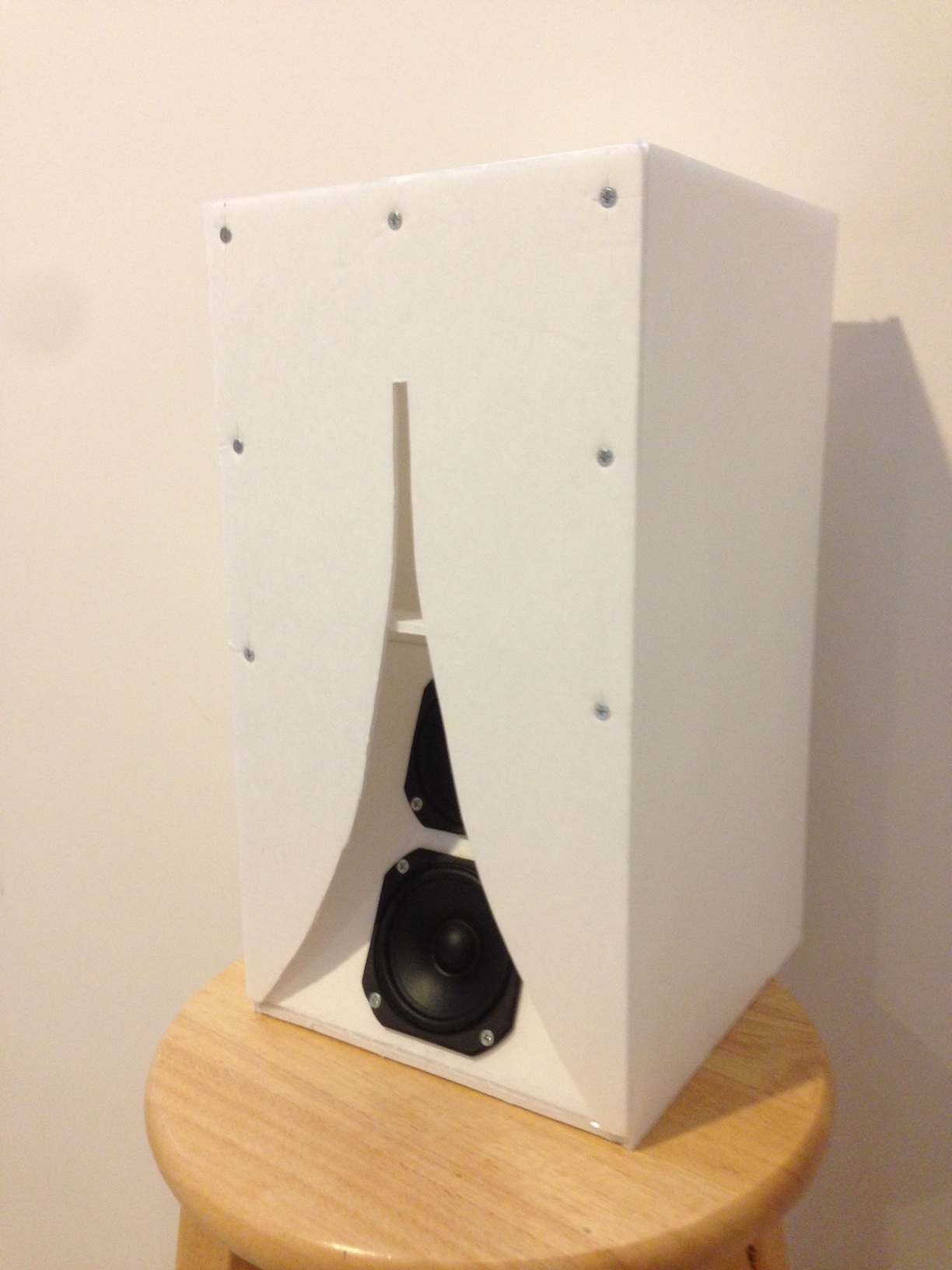
Folded design below.
Please say "No," if you don't have the time.
XRK,
I know you have tons of projects in the works. However, in my attempts to become self sufficient, I used the accidental technique for this MLTL.
Could you please check my numbers? (I may have been a little too generous in my rounding.)
Driver - Vifa TC9FD 18-08
Volume of the box - 1200 in^3, 5in X 6in X 40in
Vent - 1.5in X 5in X 8.25in
Folded design below.
Please say "No," if you don't have the time.
Attachments
AMLTL for Vifa TC9FD & Optimization with AkAbak
Jhutka,
The AMLTL you have could work, although the tuning is a bit too deep and the driver won't perform very well as the bass amplitude will really fall off. The default WinISD tuning freq is 55 Hz for the TC9FD. I would tune it higher as a bass reflex - circa 65 to 70 Hz and then let the MLTL action pull the tuning lower. The volume you have is also a bit too big (almost 21 liters) and causes a large bass peak overshoot followed by a sag in SPL. The default volume is 16 liters for the TC9FD.
So if I were to do this as a AMLTL, I would use the default volume of 16 liters, tune to 70 Hz, and the vent would be 5 in wide x 1.5 in tall x 4.8 in long. The length of the TL is set at 42.25 to allow room for the vent shelf, will dictate that the depth of the channel be about 4.6 in for a 5 in wide channel.
However, one can try to make the cabinet a little more compact by reducing the volume even further and it will still work. For a 3.5 in deep channel, the volume will be about 12 liters. For a 5 in x 1.5 in vent, the length will be 7.16 in long for 70 Hz tuning.
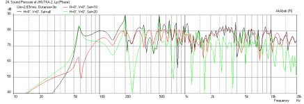
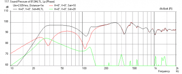
Since I now have the ability to model this in AkAbak, we can see the effect of the volume and vent as follows. The first plot is the freq response for the AMLTL that you designed (6 in deep channel with 8.25 in long vent). The tuning is really to far down around 46 Hz. The Vifa should not be pushed this low as its fs is 120 Hz. You can see the effect of a volume that is larger than optimum in the exaggerated bass peak.
Next plot is using the default 16 liter volume (4.6 in deep) and 70 Hz tuning in WinISD (7.16 in long vent). Note that the actual tuning frequency as a MLTL is now sub 50 Hz - a -20 Hz freq extension. However, there is still an exaggerated bass peak and a sag after the peak.
So we can reduce the volume to 12 liters (3.5 in deep) and reduce the vent length to 4.5 in long in order to boost the bass amplitude but give up some extension to the mid 50 Hz range, and also try to reduce the bass overshoot peak. Third plot shows the freq response for this semi optimized configuration. The cabinet will now be smaller at only 11.25 in deep (assuming 0.75 in thick stock). Note that the bass amplitude is now high enough that you don't need a BSC.
All of the sims assume that the back wall is 60 in away to remove the wall bass enhancement effect and the measurement is at 3 m away - a typical listening position as no one listens at 1 m away.
The next plot is the impedance for the 3.5 in deep case, and the last plot shows cone displacement for the 3.5 in deep case.
I hope this helps answer your question. I would go with the 3.5 in deep version with the 4.5 in long vent. You will get a fuller sounding bass and not require BSC.
XRK,
I know you have tons of projects in the works. However, in my attempts to become self sufficient, I used the accidental technique for this MLTL.
Could you please check my numbers? (I may have been a little too generous in my rounding.)
Driver - Vifa TC9FD 18-08
Volume of the box - 1200 in^3, 5in X 6in X 40in
Vent - 1.5in X 5in X 8.25in
Folded design below.
Please say "No," if you don't have the time.
Jhutka,
The AMLTL you have could work, although the tuning is a bit too deep and the driver won't perform very well as the bass amplitude will really fall off. The default WinISD tuning freq is 55 Hz for the TC9FD. I would tune it higher as a bass reflex - circa 65 to 70 Hz and then let the MLTL action pull the tuning lower. The volume you have is also a bit too big (almost 21 liters) and causes a large bass peak overshoot followed by a sag in SPL. The default volume is 16 liters for the TC9FD.
So if I were to do this as a AMLTL, I would use the default volume of 16 liters, tune to 70 Hz, and the vent would be 5 in wide x 1.5 in tall x 4.8 in long. The length of the TL is set at 42.25 to allow room for the vent shelf, will dictate that the depth of the channel be about 4.6 in for a 5 in wide channel.
However, one can try to make the cabinet a little more compact by reducing the volume even further and it will still work. For a 3.5 in deep channel, the volume will be about 12 liters. For a 5 in x 1.5 in vent, the length will be 7.16 in long for 70 Hz tuning.
Since I now have the ability to model this in AkAbak, we can see the effect of the volume and vent as follows. The first plot is the freq response for the AMLTL that you designed (6 in deep channel with 8.25 in long vent). The tuning is really to far down around 46 Hz. The Vifa should not be pushed this low as its fs is 120 Hz. You can see the effect of a volume that is larger than optimum in the exaggerated bass peak.
Next plot is using the default 16 liter volume (4.6 in deep) and 70 Hz tuning in WinISD (7.16 in long vent). Note that the actual tuning frequency as a MLTL is now sub 50 Hz - a -20 Hz freq extension. However, there is still an exaggerated bass peak and a sag after the peak.
So we can reduce the volume to 12 liters (3.5 in deep) and reduce the vent length to 4.5 in long in order to boost the bass amplitude but give up some extension to the mid 50 Hz range, and also try to reduce the bass overshoot peak. Third plot shows the freq response for this semi optimized configuration. The cabinet will now be smaller at only 11.25 in deep (assuming 0.75 in thick stock). Note that the bass amplitude is now high enough that you don't need a BSC.
All of the sims assume that the back wall is 60 in away to remove the wall bass enhancement effect and the measurement is at 3 m away - a typical listening position as no one listens at 1 m away.
The next plot is the impedance for the 3.5 in deep case, and the last plot shows cone displacement for the 3.5 in deep case.
I hope this helps answer your question. I would go with the 3.5 in deep version with the 4.5 in long vent. You will get a fuller sounding bass and not require BSC.
Attachments
Thank you for your info and time. You've helped a lot. If nothing else, I need to get AkAbak running. Also, I don't have the knowledge to tweak things. Where I am right now, I cannot see data on a graph and know which dimensions to change to make it better. My linux system is in a room we are currently using for storage as we change the flooring in other rooms. So, no advancement on the AkAbak front.
Thanks again for the effort. What I love about this forum is very knowledgeable people who are willing to help.
JHutka
Thanks again for the effort. What I love about this forum is very knowledgeable people who are willing to help.
JHutka
Vent - 1.5in X 5in X 8.25in
FYI, there’s an elbow in the vent, so its considerably longer than 8.25”.
FWIW, I checked this driver out when ya'll started showing some interest awhile back and since it has a similar path-length, I adapted it to your’s o.d. dims, driver/floor distance and it came out something like this:
GM
Attachments
![Vifa TC9FD-18-08 58 Hz MLTL [dual].gif](/community/data/attachments/322/322530-5656726cba09456c2c60aebb4c4ee303.jpg)
![Vifa TC9FD-18-08 58 Hz MLTL [dual] - response plot.gif](/community/data/attachments/322/322535-78deb92356b4533960bbadbe46c76681.jpg)
??? I haven't yet done any AkAbak designing, but if I understand you correctly, the vent is somewhat longer acoustically than you indicate and as you can see from my adaptation, don't see any point in having such a large, long vent for even two of this driver since the TL is already long enough.
GM
GM
I just meant that in my sim of design 'as drawn' I included the effect of that extended lip formed by the top edge of the shelf vent, which I thought you referred to as an elbow. Yes, the vent is way too long hence the spikey bass peak followed by a sag in response was there in the sim (when modeled without damping). That is why the optimized model ended up with a vent only almost half as long.
JHutka,
Plans look great! I look forward to seeing the build and hearing from you how it sounds. By the way, it looks like you are a fan of the Vifa driver so you may be interested in the mini Karlsonator that I built with dual TC9FD's - it's in the Foam Core thread (http://www.diyaudio.com/forums/full-range/223313-foam-core-board-speaker-enclosures-191.html#post3562928) - awesome sounding speaker that is 8 wide x 8.5 deep x 15 in tall.
Plans look great! I look forward to seeing the build and hearing from you how it sounds. By the way, it looks like you are a fan of the Vifa driver so you may be interested in the mini Karlsonator that I built with dual TC9FD's - it's in the Foam Core thread (http://www.diyaudio.com/forums/full-range/223313-foam-core-board-speaker-enclosures-191.html#post3562928) - awesome sounding speaker that is 8 wide x 8.5 deep x 15 in tall.
Last edited:
Big 12 in coaxial driver AMLTL
Is this a reasonable frequency response for a 12 in driver? I used AMLTL method to size the vents. This design is for an off-spec Eminence Beta 12CX with a higher Qts 0f 0.63 - which makes the cabinet huge. The design ended up as a 22.5 in wide x 22.5 in deep x 56.5 in tall tower. Using 3/4 in ply should make this a 2x2 ft x 5 ft tall tower - almost a refrigerator size.
The driver is at 14 in from the top and the qnty 4, 4 in dia x 4.0 in long vents are located at 8 in from the bottom and one on each wall.
Is this a reasonable frequency response for a 12 in driver? I used AMLTL method to size the vents. This design is for an off-spec Eminence Beta 12CX with a higher Qts 0f 0.63 - which makes the cabinet huge. The design ended up as a 22.5 in wide x 22.5 in deep x 56.5 in tall tower. Using 3/4 in ply should make this a 2x2 ft x 5 ft tall tower - almost a refrigerator size
. The driver is at 14 in from the top and the qnty 4, 4 in dia x 4.0 in long vents are located at 8 in from the bottom and one on each wall.
Attachments
- Home
- Loudspeakers
- Full Range
- Accidental MLTL Technique