Thanx for that reminder. Too many box designsDefinitly some verion control issues with those files. I have updated the links.
dave
Speaking of updates. Did Scott ever release a Labyrinth for the larger Alpair 7.3 ?
Finally, an update on my dual 3FE25-16 diver 0.53x Karlsonator build.
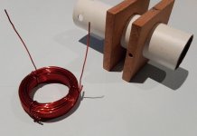
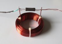
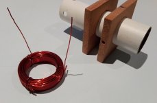
The high frequencies started to irritate my ears. After a lot of discussion with XRK971 (in another thread) about baffle step correction, I wound two 0.9mH air core inductors. Below is a picture showing the jig I made from 50mm OD steel pipe and some MFD. I used 123 turns 1.15 dia (17 gauge) magnet wire to wind the choke.
1 Ohm 5W resistors seem to have just the right amount of high frequency suppression, but I'm still experimenting.
The addition of baffle steps turned the very enjoyable (but a bit too bright and bass-lacking) 0.53X K's into mature and sweet sounding speakers with plenty bass. So, if anyone considers going the same dual FaitalPro driver route with their Karsonators, be aware that you might need BSC's.
Attachments
Last edited:

Greetings:
I'm in the process of finishing my ACA (scored a pair of boards and some parts at Burning Amp) and was starting the process of looking for an appropriate set of speakers.
I liked the Metronome speakers I saw at BA, but didn't think to ask what was loaded in them. Obviously, the choice of driver will direct the exact dimensions of the Met, and that is what brought me to this thread.
What speakers would sound good in a Met, and still be sensitive enough to provide some punch/volume on an ACA?
If I can't get everything in one speaker (without spending over about $200 on the drivers), I'd prefer a solid top end, and I'll add a sub to fill the bottom at a later time.
Ok, the amp (pair) is finished. Lots of little issues, mostly related to me trying to move too fast, but worked out well in the end.
I ended up using some old car speakers (Blaupunkt TSc660 woofer/tweeter pairs, 4 ohm nominal) in small MDF boxes. (abnout .13cu ft). Even with their (probably inflated) specs of 88/91 dB (at 1/2.83), I have no need to turn it all the way up. This is with 24v, R15 2K2 and R12 39K2, so it's pretty much loaded for bear.
Hopefully after Christmas, I can set up my little oscilloscope-in-a-box and take some measurements. Thanks for the ideas and help!
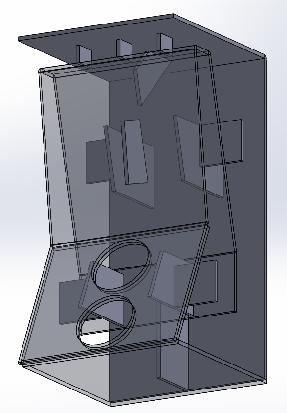
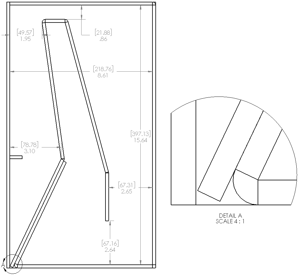
Here is the latest revision drawing of the 0.53x Karlsonator for dual FaitalPro 3FE25 drivers.
Greetings Skylar:
I have a question about the difference between what you designed (the 12mm thick parts shown in post 73 of this thread) and what you built (the thin foam-core shown in post 83). I'm looking to build the same thing, and was wondering if you scaled any of the dimensions for the much thinner foam version or not?
I have a line on some 1/2" polystyrene which I was considering for building to your plan (post 73). Any thoughts or concerns? Locally I seem to only be able to find foam-board that's barely stiffer than the cardboard backing on a pad of writing paper, designed for children's book reports and science projects. I figured that probably wasn't stiff enough, but really had no idea.
A related question - where do you stand on building of the light (thin) plywood version? Have you started, or is that project still on hold? I've worked extensively in wood, and would prefer that, but was concerned with comments regarding the change in how things sounded.
Hi Ken
I didn't build to the plan for 12mm MDF that I posted. I have used the Karlsonator_.53x_Dual_Vifa_TC9FD.pdf plan that was posted in the Mini Karlsonator (0.53X) with Dual TC9FD's thread, instead. But I had to enlarge the driver baffle to accommodate the dual 3FE25's with a few mm clearance between the drivers. I'll post the PDF below.
I doubt that 1/2" Polystyrene will work well, but maybe someone else with experience of it can comment.
I'm still planning to re-build the 0.53X's using LitePly, which is poplar and much lighter than Birch ply, but I haven't done so yet.
Christo
Attachments
Hi Ken
I didn't build to the plan for 12mm MDF that I posted. I have used the Karlsonator_.53x_Dual_Vifa_TC9FD.pdf plan that was posted in the Mini Karlsonator (0.53X) with Dual TC9FD's thread, instead. But I had to enlarge the driver baffle to accommodate the dual 3FE25's with a few mm clearance between the drivers. I'll post the PDF below.
I doubt that 1/2" Polystyrene will work well, but maybe someone else with experience of it can comment.
I'm still planning to re-build the 0.53X's using LitePly, which is poplar and much lighter than Birch ply, but I haven't done so yet.
Christo
Great! Thanks again for the help.
Hi Ken
I didn't build to the plan for 12mm MDF that I posted. I have used the Karlsonator_.53x_Dual_Vifa_TC9FD.pdf plan that was posted in the Mini Karlsonator (0.53X) with Dual TC9FD's thread, instead. But I had to enlarge the driver baffle to accommodate the dual 3FE25's with a few mm clearance between the drivers. I'll post the PDF below.
I doubt that 1/2" Polystyrene will work well, but maybe someone else with experience of it can comment.
I'm still planning to re-build the 0.53X's using LitePly, which is poplar and much lighter than Birch ply, but I haven't done so yet.
Christo
A couple of quick questions:
From the look of the drawing you included, you have a part-layout program to do efficient layouts. I can't easily get foamboard in 32x40, but can get it in 20"x30".
Can you run it again with the smaller boards? Also, can you line up panels 1 & 3-6 so I can make a seamless, bendable version of the labyrinth section? Sections 1-6, skipping 2, is 28.610", if I did my math correctly. I plan to do section 2 in basswood or thin plywood. Also, thanks for the internal bracing - I was trying to figure out how to best to that.
Also, it looked like while you were in construction that you added felt or something similar to the inside. What did you end up with (interior treatment, stuffing, etc), and how much did it help?
I am aware of the home-made inductor you made, and I believe you ended up with an air-core inductor with a 50mm interior diameter, and something like 123 turns. How wide was the coil (distance between the end-boards on the pipe)? I tried back-calculating info on the link you provided, and had real trouble getting 0.9mH. Can you clarify? I also believe you ended up with a 1 ohm resistor in parallel with the coil. Is that correct? More interested in starting from a known point, so I'd rather match your configuration than start with an experiment. Once I have a baseline, I can try to mess with it, if I my ears are different than yours.
Look in 0.53x Karlsonator thread, Mudjester is making new cut and fold CAD plans for 20x30in foam core. Thanks, MJ!
Mini Karlsonator (0.53X) with Dual TC9FD's
He's almost done, I think.
Mini Karlsonator (0.53X) with Dual TC9FD's
He's almost done, I think.
I am aware of the home-made inductor you made, and I believe you ended up with an air-core inductor with a 50mm interior diameter, and something like 123 turns. How wide was the coil (distance between the end-boards on the pipe)? I tried back-calculating info on the link you provided, and had real trouble getting 0.9mH. Can you clarify? I also believe you ended up with a 1 ohm resistor in parallel with the coil. Is that correct? More interested in starting from a known point, so I'd rather match your configuration than start with an experiment. Once I have a baseline, I can try to mess with it, if I my ears are different than yours.
The coil is 20mm high (wide). I used to use a 1.5 Ohm resistor, but am now listening with 2.2 Ohm. It dampens the highs a little more.
But as X said, adjust (the resistor) to taste. I'd start with 2.2 Ohm and try a few other values, between 1 and 4.7 Ohm to hear the difference.
Inductors
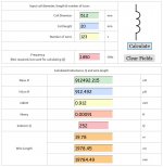
I have used the M0UKD Air Cored Inductor Calculator to design my 0.9mH inductors. The values used were:
The coil length should have been18.8mm to the center of the wire, but even with that correct, the inductance doesn't vary much (0.94mH). 120 Turns would make it 0.895mH.
Play around with the calculator and see what you get.
I have used the M0UKD Air Cored Inductor Calculator to design my 0.9mH inductors. The values used were:
Coil diameter: 51.2mm (center to center of wire)
Coil length: 20mm
Number of turns: 123
(I kept the default 1.850 frequency)
The result is a 0.9mH choke. I've used 1.2mm wire for very low resistance (0.29 Ohm).Coil length: 20mm
Number of turns: 123
(I kept the default 1.850 frequency)
The coil length should have been18.8mm to the center of the wire, but even with that correct, the inductance doesn't vary much (0.94mH). 120 Turns would make it 0.895mH.
Play around with the calculator and see what you get.
Attachments

Pass DIY Addict
Joined 2000
Paid Member
I've done the same thing with my Tang Band 1772 speakers and my FHXL with 10.3 metal cone drivers. Taming the highs was simple experimentation and made both speakers much more enjoyable to me! I rather enjoy the tweak-to-taste approach to dialing in the response curve for my speakers.
Both are excellent candidates for the ACA!
Both are excellent candidates for the ACA!
Hard to say. The spec says 90 dB sensitivity and 1W/1m, but sensitivity would be 2.83 V into 16Ω which is a half-watt. So they could be 90 or 93 dB 1W/1m depending on which part of the spec is a mis-truth. Add a secound driver get 3 dB more level, add 2 more for 3dB more, and adjust for impedance. Sensitivity & 1W/1m will be different.
dave
dave
Hey Skylar88 & xrk971
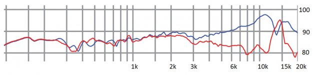
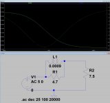
I've been looking at the frequency response of the 3FE25-16, and noticed that there's a bump at 2kHz, and that there is a rise starting at 3k, passing thru about +6dB at 6k and on to about 10-12dB at 12k before falling off. I presume these are the 'honk' and 'ear fatigue' peaks mentioned in discussions about the baffle step circuit.
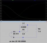
However, looking at what Skylar88 is using (0.9mH & 2R2) and putting it in a simulation with 7.5 ohms as the load, about the average between 3k & 12k (based on the graph provided by the manufacturer), I got about a 2dB cut way earlier than expected and being about 1dB down at about 450-500Hz. Using a similar inductor and the 4R7 recommended by xrk971, I got about 4dB of hi freq cut, with the curve passing thru the -2dB point at about 700Hz.
This is not what I expected to see, based on what was discussed. In theory, if I read it correctly, I was expecting the filter not to start cutting until about 1k (which, based on what the speaker graph, seems to be a bit early). I played with the circuit to try to get the silly thing to do what I think it should do (start cutting around 1K, show some decrease by 3k, -6dB at 6k and -12dB at 12k) and ended up with a 0.3mH (at 0.3 ohm) and a 47 ohm resistor. I got about -2dB at 3k, -7.5dB at 6k and -10dB at 12k. However, it was still dropping like a rock, so by 20k, it was down over 14db and still falling.
I obviously don't understand something. I thought the baffle step was there to help level the speaker response. Am I getting a little carried away?
PS -Skylar88 - I tried building the same inductor you did, and came up with (using a $12 kit inductor-meter) 0.903mH and about 0.7 ohms for 17ga wire (a little thinner than yours). The online calculator came out better than expected. I used 2" outer diameter (50.8mm) plumbing adapter, cut to 20mm long and plates bolted on each end as a form.
I've been looking at the frequency response of the 3FE25-16, and noticed that there's a bump at 2kHz, and that there is a rise starting at 3k, passing thru about +6dB at 6k and on to about 10-12dB at 12k before falling off. I presume these are the 'honk' and 'ear fatigue' peaks mentioned in discussions about the baffle step circuit.
However, looking at what Skylar88 is using (0.9mH & 2R2) and putting it in a simulation with 7.5 ohms as the load, about the average between 3k & 12k (based on the graph provided by the manufacturer), I got about a 2dB cut way earlier than expected and being about 1dB down at about 450-500Hz. Using a similar inductor and the 4R7 recommended by xrk971, I got about 4dB of hi freq cut, with the curve passing thru the -2dB point at about 700Hz.
This is not what I expected to see, based on what was discussed. In theory, if I read it correctly, I was expecting the filter not to start cutting until about 1k (which, based on what the speaker graph, seems to be a bit early). I played with the circuit to try to get the silly thing to do what I think it should do (start cutting around 1K, show some decrease by 3k, -6dB at 6k and -12dB at 12k) and ended up with a 0.3mH (at 0.3 ohm) and a 47 ohm resistor. I got about -2dB at 3k, -7.5dB at 6k and -10dB at 12k. However, it was still dropping like a rock, so by 20k, it was down over 14db and still falling.
I obviously don't understand something. I thought the baffle step was there to help level the speaker response. Am I getting a little carried away?
PS -Skylar88 - I tried building the same inductor you did, and came up with (using a $12 kit inductor-meter) 0.903mH and about 0.7 ohms for 17ga wire (a little thinner than yours). The online calculator came out better than expected. I used 2" outer diameter (50.8mm) plumbing adapter, cut to 20mm long and plates bolted on each end as a form.
Attachments
You may want to try a line level BSC circuit, the one Rod Elliot outlines is simple, effective, and adjustable via pot. Less interaction with the speaker itself.
Baffle Step Compensation
Or here-
Passive Line Level Baffle Diffraction Step Compensation
Baffle Step Compensation
Or here-
Passive Line Level Baffle Diffraction Step Compensation
PS -Skylar88 - I tried building the same inductor you did, and came up with (using a $12 kit inductor-meter) 0.903mH and about 0.7 ohms for 17ga wire (a little thinner than yours). The online calculator came out better than expected. I used 2" outer diameter (50.8mm) plumbing adapter, cut to 20mm long and plates bolted on each end as a form.
Good to know, Ken. Thanks for confirming that the calculator can be trusted. Btw, I have been listening to my dual driver K's, without and with BSC. There is quite a reduction in SPL with the BSC. If my ears could handle the natural high frequency boost (of the dual drivers), I would much rather go without the BSC, in combination with the fleawatt ACA and B1 buffer.
In hindsight, the B1 may not have been the best preamp option for the ACA in my system. I'm therefore planning to build a new preamp with gain (AKSA Lender) to hopefully get better SPL out of the ACA and Karlsonator (with BSC) combination. I know the Karlsonators can do it, but whether the ACA can deliver more remains to be seen.
If you make the Alpha 20, you get the Aksa Lender Preamp as the front end to the amp and 20w which should be more than enough for the Karlsonator. I never used a BSC on my Karlsonators - I always felt they were pretty well balanced and not too bright. But then never had a dual 16ohm one.
KKing, the BSC May prove to be different if you model the speaker with appropriate elements equivalent to real driver (RLC equivalent of TS parameters).
I can run a simulation in Akabak with and without BSC and let’s see how it looks.
KKing, the BSC May prove to be different if you model the speaker with appropriate elements equivalent to real driver (RLC equivalent of TS parameters).
I can run a simulation in Akabak with and without BSC and let’s see how it looks.
- Status
- This old topic is closed. If you want to reopen this topic, contact a moderator using the "Report Post" button.
- Home
- Loudspeakers
- Full Range
- ACA Speaker short list