Hi Peter,
An AC synchro motor requires a 90* phase shifted signal to run, usually derived from a cap. But the lowest vibration that the motor can exhibit will often come at a different phase shift, usually within 10* of 90, and will vary with different motors. Either burn a disc with a number of different phase shifts, and testing the motor for vibration, or using your soundcard output and varying the phase for minimum vibration, then burning a disc from those settings.
My Gyro motor is only 20V, so I could probably run it directly from a small amp I already have, 1 channel per phase. Might hit the stores today and see if I can pick up a cheap CDP, and burn a couple of CDs (no soundcard). I'd prefer to do this all solidstate, but I do like to irony of a CDP being the mere controller of my TTs motor, and it's also cheap and easy to implement. Later I will use the DC motors and a tape drive I'm getting through Bernhard.
Of course my SP10's don't need any such frippery.
Cheers
Brett
Brett
You seem to like your SP10. I still keep my L07D too but only because shipping it to a willing buyer will be more expensive than anyone sane will pay (35kg). Writing two phase shifted sines to a CD never crossed my mind, have to admit it's a brilliant idea, but adjusting the phase shift is of course a bitch. From what i understand the optimal shift is specific to every motor. I built a simple 90s8015 based oscillator for my synchronous TTs which outputs two shifted sines at two of its ports with any preset shift. It uses a lookup table to generate the sines and using 100 points per cycle and a DAC0800 followed by 12db/oct filter at output i get about 0.01% distortion, similar to the Wien bridge.
May every cd player end up driving a TT one day.
peter
Typical synchronous motors only need about 3W, which is less than 20mA rms per winding at 90V. This is easy to achieve from a simple chip amp and pair of step up transformers.
Step up is the safest way to do this, 90V rms is already a hazardous voltage. You don't want a driver amplifier running off +/- 150 Vdc rails.
Step up is the safest way to do this, 90V rms is already a hazardous voltage. You don't want a driver amplifier running off +/- 150 Vdc rails.
I am designing an AC power supply for my turntable (VPI HW-19), something along the lines of the VPI 'electronic flywheel'. The goal is an accurate, 60/81.8 Hz (33/45 RPM) 120 VAC sine wave generator, approx .5 amp capacity.
What I have in mind is: accurate low level adjustable oscillator, into a class B amp module, output of which would go to a step up transformer.
I realize that this may not be the most refined approach, but I am not an electronics desigh specialist, I am more of a systems person.
I would appreciate any comments from the group.
Refer to the attached file for a block diagram.
Gilid,
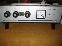
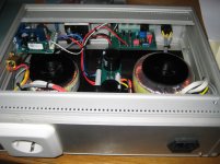
You can build this supply I did this for my Thorens TD124 and Garrard 301 and 401 turntables, 50 hz Wien oscillator and poweramp .
It is amazing how much better the sound is from the turntable I did also some measurements between the mains supply and the dedicated supply concerning distorsion ,
see picture from the supply
Volken
Attachments
Gilid,
You can build this supply I did this for my Thorens TD124 and Garrard 301 and 401 turntables, 50 hz Wien oscillator and poweramp .
It is amazing how much better the sound is from the turntable I did also some measurements between the mains supply and the dedicated supply concerning distorsion ,
see picture from the supply
Volken
This looks interesting.. Do you have plans to publish the design or can we nicely request you post the schematics?

..can we nicely request you post the schematics?
Please
- Status
- This old topic is closed. If you want to reopen this topic, contact a moderator using the "Report Post" button.
- Home
- Source & Line
- Analogue Source
- AC Motor Power Supply Project