So update.... I finally had success tonight stretching and attaching the membrane to the stator panel.
I got something like a 1.5% stretch.... however I strongly suspect the stretch is tighter in the middle than the ends of the panel judging from how the bike tire was inflated.
As you can see, I got my stretch horizontally and not so much vertically (which is what I believe I was want anyways with my vertical spacers).
I gave up on the double sided tape and instead I taped the bottom perimeter of the mylar with the lowes tape (I believe it is tyvek tape) for reinforcement and then used gorilla tape that sticks to that and to the MDF underside of the jig.
I inflated the tube a bit to get the wrinkles out and put a little stretch in it... At that point, I put some of the lowes tape over top of the mylar in the corners (top side) - to reinforce it. Then I inflated it to its final stretch.
It may be a little tighter than I want but I figured the tape (UHB BTW) would relax a little over time and if it is really a problem I could heat gun it to loosen it up.
Per Sanders advice in his book, I wanted to err on the higher side of a stretch % for my hybrids.
I may get frisky and try testing the resonance frequency to make sure it is reasonable before I stick it all together.
One more to go, then coating, then charging ring....
I'm going to have a drink now......
I use sail clamps to clamp the mylar to the frame, just allot of them for a quad panel i use around 34

my stretch frame has 3 layers top layer with a cutout the size of the panel without spacers so you can measure the resonance the panel will be while it is on the stretch jig. then a frame of mdf of one layer and then a frame of mdf that is wider then the midle previous frame. this is where i clamp the mylar onto. so it wraps around the stretch jig and clamped on the inside.
i blow in some air, so wrinkles are gone, then only add good GAFFER tape on the corners not the cheap crap from the store but the stuff they use on film sets, take a piece thats longenough to wrap fully around the corner. then i stretch it to required resonance. i measure the resonance with a mic ontop of the mylar and a woofer under the stretch jig. play a sweep and compare it original or a new value.
if you dont want any slack to return, use a heat gun to heat the mylar in between adding more air in the tube. stretch it to the required res. heat it, remeasure and you will see it dropped. add more air heat it. do this a few times and you will notice the drop becomes less and less. i usually do this 2 or 3 times.
its in fact what quad did with there panels , be it under more controlled way. adding weights and then just put the whole thing in the oven, the mylar will relax and the weights will kmeep the reosnance the same at all time. when it cools down the mylar is stable and wont change over time. i got 3 panels here one from serial nr 3000 and one from 30000 and they are almost identical , its hard to beat.
Last edited:
So need some advice here.....
I used a little speaker and a tone generator and I believe the resonance of my panel is 200HZ. I see the most "excitement" around the frequency but I also see movement a little lower around 150Hz.
So this is quite a bit higher than I was shooting for...as I wanted to crossover somewhere around 300Hz.
Lesson learned here... not so much tension..... but I was thinking of going over the mylar with my heat gun on a low setting to trying and lower the tension (thus resonance frequency).
Good idea, bad idea?
Do I go ahead and make the 2nd panel the same way with the same tension (and heat treat) or do I make it with lower tension?
I'm kind of curious what happens if you have 2 panels that are not "tuned" the same (presume bad things with imaging etc...)
my stretch frame has 3 layers top layer with a cutout the size of the panel without spacers so you can measure the resonance the panel will be while it is on the stretch jig. then a frame of mdf of one layer and then a frame of mdf that is wider then the midle previous frame. this is where i clamp the mylar onto. so it wraps around the stretch jig and clamped on the inside.
Could you post a few pictures of your jig? (or links if you already have!).I would love to see it.
I don't think your imaging will suffer that much with differing resonant frequencies, as most imaging awareness happens a little higher. (might be hypersensitive though)
However, I do think this high reading will affect your x-over decision.
Personally, I'd (as much as it sucks) re-do the panel with less tension to utilize your original x-over choice.
These are just my general thoughts after a similar miscalculation on my curved panels ...(plus a couple drinks on a Friday)..D'oh!
Please..someone else with more knowledge chime in...
Last edited:
Hi,
As You can learn from ML, who only stretch but don´t treat thermally (they can´t due to the membrane material properties), their panles require up to 1/2 a year to settle to the final working points.
Over this period of time the resonance frequency drops considerably.
The sonics also improve as the panel finally ´fit´ their xover.
Thermal treatment reduces the resonance frequency and pre-ages the membrane.
Uneven amounts of stretch over the membrane area are harmonized.
After treatment the membrane behaviour remains almost constant.
I use thermal treatment with my curved panles also, resulting in a very short break-in period (just a couple of hours).
A fs >200Hz hints towards off-optimal free distances of the membrane.
How thick is Your membrane and what are the free vibrating distances and what d/s do You use?
Maybe You could increase spacer distances.
jauu
Calvin
good idea, most definitely.Good idea, bad idea?
As You can learn from ML, who only stretch but don´t treat thermally (they can´t due to the membrane material properties), their panles require up to 1/2 a year to settle to the final working points.
Over this period of time the resonance frequency drops considerably.
The sonics also improve as the panel finally ´fit´ their xover.
Thermal treatment reduces the resonance frequency and pre-ages the membrane.
Uneven amounts of stretch over the membrane area are harmonized.
After treatment the membrane behaviour remains almost constant.
I use thermal treatment with my curved panles also, resulting in a very short break-in period (just a couple of hours).
A fs >200Hz hints towards off-optimal free distances of the membrane.
How thick is Your membrane and what are the free vibrating distances and what d/s do You use?
Maybe You could increase spacer distances.
jauu
Calvin
Any chance you can get a measurement with microphone near the diaphragm so we can see exactly what is going on?...I used a little speaker and a tone generator and I believe the resonance of my panel is 200HZ. I see the most "excitement" around the frequency but I also see movement a little lower around 150Hz.
Also, if possible, use a speaker with resonance well below where the diaphragm modes are.
When you first apply diaphragm to your curved panels, do you use the usual method for curved panels of high tension in height direction and low tension in width?...I use thermal treatment with my curved panles also, resulting in a very short break-in period (just a couple of hours).
When you later thermally treat the diaphragms, I would think the tension in the height direction would be reduced but tension in the width direction increased. Doesn't this result in the diaphragm curving toward the rear stators in the middle of each horizontal diaphragm section? Or maybe it does, but is just not enough to worry about with hybrid ESL having sufficient radiating area.
My only experience with heat-treating Mylar was to tighten loose spots in ESL diaphragms. (main reason I posted what I did last night)
Didn't know it could be used to relax overly tensioned as well...hmm..
Is the heat-treating a 'normalizer' of sorts, or??
In any event, very interested in learning more about this.
Didn't know it could be used to relax overly tensioned as well...hmm..
Is the heat-treating a 'normalizer' of sorts, or??
In any event, very interested in learning more about this.
Hi,
good idea, most definitely.
Uneven amounts of stretch over the membrane area are harmonized.
After treatment the membrane behaviour remains almost constant.
I use thermal treatment with my curved panles also, resulting in a very short break-in period (just a couple of hours).
A fs >200Hz hints towards off-optimal free distances of the membrane.
How thick is Your membrane and what are the free vibrating distances and what d/s do You use?
Maybe You could increase spacer distances.
jauu
Calvin
To answer your question, my free distance (I presume you mean the space between my vertical spacers) is about 5"..... thus which is why I am leaning toward being a little over tensioned.
Funny you mention the "harmonizing" effect of heat treatment because I was thinking and curious about the same thing. It is somewhat obvious from touch and from looking at my membrane, the tension is not exactly even. I was thinking the heat gun would have an "annealing" effect like it does in glass.
I was so curious I actually look a polarized light source - which a white LCD screen happens conveniently be - and looked thru a polarizing filter to see if I could see the strain in the diaphragm.... unfortunately my crude attempt didn't yield anything useful. This method is used to detect strain in optical glass but I'm not exactly sure this will work on the 6um thin mylar and its optical properties(e.g. index of refraction et al).
I may mess around with it some more.... I am kind of curious as to what the effect of strain in the membrane would be on sonic performance. I would think it is important and maybe why other manufacturers "baked" their panels once the membrane was applied.
Just a quick update....
So I took my heat gun to it and made a *big* difference.... dropped the resonance down to 114hz almost exactly. I get the most "visible" excitement at this frequency consistently across the membrane... there are other modes of excitement as well but this one is quite obvious.
The bad news is I burned a tiny hole in the membrane with the heat gun. I put a little piece of the tyvek tape over it. It is on the bottom and not terribly visible so I may just live with it. Haven't decided yet...
It appears there is less strain in the membrane just from the "rainbow" diffraction patterns I was seeing before under fluorescent light, they were all twisted....now they are fairly straight and less visible. I will try photographing it on the next one but suspect it will be difficult.
I will probably do my next panel the same way... I like the idea of going a little over with tension then heat treating it "anneal" it out. No idea at all if it makes any sonic difference, just seems like it should.
I did also want to note that I plan on covering my panels with silk screen for damping.
Awesome, that's great news!
Also one hell of an "Aha!" moment for me, I had no idea...
New one in my book, and a game changer as far as I'm concerned.
If you're going to be covering these, I wouldn't let the burn bother me unless it affects the sound negatively..
Roll with it bengel, you're almost done, haha..

Also one hell of an "Aha!" moment for me, I had no idea...
New one in my book, and a game changer as far as I'm concerned.
If you're going to be covering these, I wouldn't let the burn bother me unless it affects the sound negatively..
Roll with it bengel, you're almost done, haha..
Last edited:
I'm back again for an update on my insanely long ESL project.... it sucks in that literally every weekend for the past 6+ months I've been busy with other projects....
At any rate.... onward.... so I managed get the diaphram on my second panel; after *several* attempts at stretching.... I did it the same way as my last one.
My excited resonance frequency was about 132hz right off the stretching jig (well, I did let it sit overnight). I applied a few rounds of heat treatment and got it down to about 124hz. I stopped as I was getting uncomfortable how long I was having to go over it with my heat gun on full blast.... I didn't want another hole.
So I have one at 114hz (as of my measurement a few months back) and one at 124hz... close enough I guess.
Also noteworthy, is I do have other modes of excitement under 124... like a big one (smaller than 124 though) around 65hz.... about an octave so kind of makes sense.
I have become a fan of heat treating after stretching. The one thing I cannot get a good picture of is the diffraction you see when you look at fluorescent light at a "glancing" angle across the diaphragm.
Before I heat treat, the rainbow patterns (for lack of a better word) are twisted, clumped etc... all across the membrane surface, after heat treatment they are pretty much straight up and down. I could be wrong, but this is telling me the tension of the diaphragm becomes more uniform after treatment. I have no idea if this has any impact sonically.
Next is coating.... electronics, then some more woodworking.
Got the coatings sprayed on... though I think I went a little overboard with the spray.
I tested both panels for resonance and they both come in right around 124hz after the coatings. Not sure why my older panel increased in resonance or if my testing method is sound but at least they are consistent between the 2.
Some largeish dust particles settled into the coating, should I remove them (if even possible)?
I think the bigger particles will vibrate off during use and the smaller ones won't be enough to affect their sound or performance..
Someone else more knowledgable than I will probably chime in though, I'm guessing..
How much coating is leftover in the can? I used just under half a can for my 15"x60" curved panels, that's probably overkill too, but I wanted to make sure they had full coverage. (plus a bunch wound up on a foam brush I used to spread it out)
Congrats on getting getting closer to completion, any pics you could post up?
Maybe a pic of the dust too, so someone could form a better opinion?
Cheers
-Steve
Last edited:
Glad to hear you are still making progress, and closing in on completion.Also noteworthy, is I do have other modes of excitement under 124... like a big one (smaller than 124 though) around 65hz.... about an octave so kind of makes sense.
I wonder if the 124Hz resonance is the lowest mode, and is just being excited by the 65Hz tone.
Were you ever able to get a microphone to measure the actual response? That would let you know for sure.
Fortunately even a thick coating of Licron Crystal adds little mass.Got the coatings sprayed on... though I think I went a little overboard with the spray.…Some largeish dust particles settled into the coating, should I remove them (if even possible)?
http://www.diyaudio.com/forums/planars-exotics/186840-david-lucas-esl-6.html#post3610816
I doubt the dust particles will cause any problem whatsoever.
But, if it bothers you, you can remove them with a Qtip dipped in acetone.
Then reapply a bit of Licron in the area with a modeling paint brush.
I’ve done it.
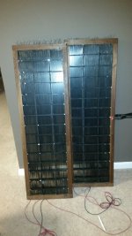
So finally got the panels together... Put the charging ring on and stuck them together.
It's worth noting that I used conductive adhesive copper tape and stuck the tape directly to the diaphragm coating (which does not go all the way to the edge).
Definitely not built to the tolerances/quality I would like them to be but hopefully they will sound good. I am concerned how accurate/consistent the d/s spacing is across the diaphragm given that hundredths of an inch matter.
I have not measured the resonance with a microphone setup. I kind of figured I've done all I can do with it anyways other than try to go lower and redo the diaphragm. I think in the long run, I will be better off with a bit higher tension/resonance anyways.
Here is a pic of the current state. Have some touch ups to do on the grid, though I may not bother as I plan to cover them with silk screen for damping.
Next on to the resistor bank. I would love to measure the capacitance of the panel to nail down the resistor values but I am not sure my meter is accurate enough or if it would be accurate anyways.
It's worth noting that I used conductive adhesive copper tape and stuck the tape directly to the diaphragm coating (which does not go all the way to the edge).
Definitely not built to the tolerances/quality I would like them to be but hopefully they will sound good. I am concerned how accurate/consistent the d/s spacing is across the diaphragm given that hundredths of an inch matter
. I have not measured the resonance with a microphone setup. I kind of figured I've done all I can do with it anyways other than try to go lower and redo the diaphragm. I think in the long run, I will be better off with a bit higher tension/resonance anyways.
Here is a pic of the current state. Have some touch ups to do on the grid, though I may not bother as I plan to cover them with silk screen for damping.
Next on to the resistor bank. I would love to measure the capacitance of the panel to nail down the resistor values but I am not sure my meter is accurate enough or if it would be accurate anyways.
Attachments
I have just finished building my $800 ER Audio 505 Mini Panel kit and the performance is sublime. Kit is plug & play. No soldering required unless you want to fine tune them.
Construction details for my build are at:
DIY audio LDR preamplifier kit projects | ER Audio ESL speaker kit
Cheers,
Rob
Construction details for my build are at:
DIY audio LDR preamplifier kit projects | ER Audio ESL speaker kit
Cheers,
Rob
...
Here is a pic of the current state. Have some touch ups to do on the grid, though I may not bother as I plan to cover them with silk screen for damping.
Next on to the resistor bank. I would love to measure the capacitance of the panel to nail down the resistor values but I am not sure my meter is accurate enough or if it would be accurate anyways.
Any updates on the build ???
TIA
- Status
- This old topic is closed. If you want to reopen this topic, contact a moderator using the "Report Post" button.
- Home
- Loudspeakers
- Planars & Exotics
- About to take the ESL plunge