
Surely that can’t be😬I can't see anything wrong ....
")
Thanks for checking.
For R13 I ordered both 300R and 330R’s. And for R17 PRP didn’t have a 5K so I ordered both 4K7 and 5K6, which one will work or should I get another brand?
Thanks
R13 not critical , just toss in first one you get
you can even put different values in channels ....... LED string doesn't mind
R17 - what's important is sum of R17 and R18 , and that they are so so equal in value , to have equalish dissipation
just put 4K7 for R17 and 5K6 for R18
you can even put different values in channels ....... LED string doesn't mind
R17 - what's important is sum of R17 and R18 , and that they are so so equal in value , to have equalish dissipation
just put 4K7 for R17 and 5K6 for R18
Hi,
think all parts are here and I can start .... nice little part (around 1/2 smaller)! ;-)
I know, 14 not 25 turns, but really small and if they not work as I think, will change them to 25 turns.
Question to the heatsink for 10w to 15W, would they fit (without the extension boards) for one channel? => Fischer SK 93/150/SA (400x40x150mm, 0,31 K/W)
Or
This one: klicki then I didn't need to make some holes .... (301x125x50mm)
Thanks for advice!
Btw, when I need more power I will go to a 4/5 unit diyaudio case but for first listening ... ;-)
think all parts are here and I can start .... nice little part (around 1/2 smaller)! ;-)
An externally hosted image should be here but it was not working when we last tested it.
I know, 14 not 25 turns, but really small and if they not work as I think, will change them to 25 turns.
Question to the heatsink for 10w to 15W, would they fit (without the extension boards) for one channel? => Fischer SK 93/150/SA (400x40x150mm, 0,31 K/W)
Or
This one: klicki then I didn't need to make some holes .... (301x125x50mm)
Thanks for advice!
Btw, when I need more power I will go to a 4/5 unit diyaudio case but for first listening ... ;-)
Last edited:

I have the daughter boards completed and bolted to the heat sinks. The thick (14 ga) wires from the power supply are now terminated. The power supply is tested and ready to go.


Ugliest amp of all. But only the heatsinks will be visible, from the side, after they are slid into the back of console they are built for.

I have a few resistors, a couple capacitors and the LED’s on order, should be here middle of next week to finish.
Zen Mod, I need help with the jfets, can you explain how to “double piggy back?
Anything pop out at you on the FE board?

Ugliest amp of all. But only the heatsinks will be visible, from the side, after they are slid into the back of console they are built for.
I have a few resistors, a couple capacitors and the LED’s on order, should be here middle of next week to finish.
Zen Mod, I need help with the jfets, can you explain how to “double piggy back?
Anything pop out at you on the FE board?
Man , you have some serious Voodoo there
one thing can't grasp - how on Earth is profitable purchasing Donut from other side of Big Splash ?
regarding input LTP :
let's call them left JFet as one position and right JFet as other position;
if one is going to simple pair of JFets in LTP, you take one pair of JFets I sent you (big letter M written on tape across two of them ) , one in one position , second in other position. no change in current through LTP , so no change in CCS above LTP
if one is going to piggyback - two pairs of JFets in LTP , you take two pairs of JFets I sent you ; call them pair A and pair B ;
use one JFet from pair A and one JFet from pair B for left position in LTP , and use remaining JFet from pair A and remaining JFet from pair B for right position in LTP
in that case , double current through LTP (halve values of R10+TP2 ), also halve value of R11 , set initial current to 20mA monitoring it across R11 ...... and halve value of R7+TP1
all that according to attached schm ; ignore fact that is for base-board-only , what counts is the same
Some progress ... wait for the heat sinks.
Mmmmh, I think they will be dual mono
An externally hosted image should be here but it was not working when we last tested it.
Mmmmh, I think they will be dual mono
An externally hosted image should be here but it was not working when we last tested it.
Man , you have some serious Voodoo there
one thing can't grasp - how on Earth is profitable purchasing Donut from other side of Big Splash ?
regarding input LTP :
let's call them left JFet as one position and right JFet as other position;
if one is going to simple pair of JFets in LTP, you take one pair of JFets I sent you (big letter M written on tape across two of them ) , one in one position , second in other position. no change in current through LTP , so no change in CCS above LTP
if one is going to piggyback - two pairs of JFets in LTP , you take two pairs of JFets I sent you ; call them pair A and pair B ;
use one JFet from pair A and one JFet from pair B for left position in LTP , and use remaining JFet from pair A and remaining JFet from pair B for right position in LTP
in that case , double current through LTP (halve values of R10+TP2 ), also halve value of R11 , set initial current to 20mA monitoring it across R11 ...... and halve value of R7+TP1
all that according to attached schm ; ignore fact that is for base-board-only , what counts is the same
Zen Mod, thanks for answering. Since I’m a dodo, can you check to see if I understand you correctly?
You sent parts for option 1 and option 2. Since I’m going for higher power I’m using option 2.
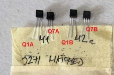
Here is a pic with my notes in blue with what I assume are correct locations. What is the preferred way to physically piggyback the jfets? Do you have a pic where it’s been done before?

I have been following this earlier schematic, for my build is this still correct?

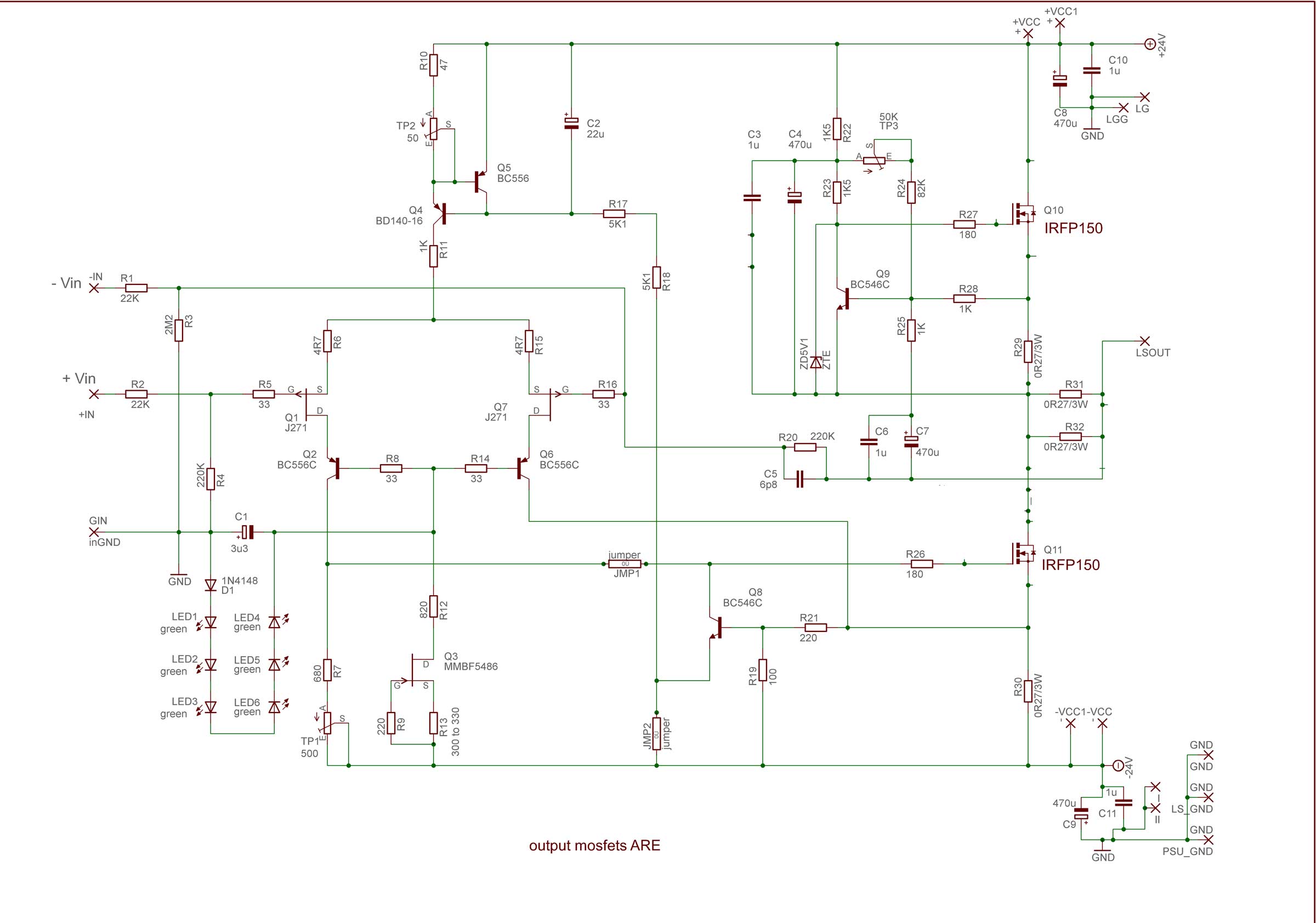
well , considering that I'm rarely drinking , I can't say that I was drunk while editing that schematic ...... simply , as I forgot to edit values of drain resistors , even if value of R11 can stay the same
will make tomorrow pic of piggy backed small critters and post for you ;
also , I'll make new edited schm , to save you from any further mistake , be it mine (or yours) responsibility
also ........ I believe that I sent you BD140s for cascodes (Q2,Q6) , besides/instead small BC ones ? if I didn't , another one on my conscience .........
regarding JFets distribution , look at enclosed edit of your pic ...... I believe it'll be clear this time .... meaning Q1A goes together with Q1B , Q7A goes together with Q7B
Attachments
You make me smile!well , considering that I'm rarely drinking , I can't say that I was drunk while editing that schematic ...... simply , as I forgot to edit values of drain resistors , even if value of R11 can stay the same
will make tomorrow pic of piggy backed small critters and post for you ;
also , I'll make new edited schm , to save you from any further mistake , be it mine (or yours) responsibility
also ........ I believe that I sent you BD140s for cascodes (Q2,Q6) , besides/instead small BC ones ? if I didn't , another one on my conscience .........
regarding JFets distribution , look at enclosed edit of your pic ...... I believe it'll be clear this time .... meaning Q1A goes together with Q1B , Q7A goes together with Q7B
It’s all my fault to want to build overkill! I take all responsibility.
I didn’t see any BD140’s in package. Can I buy locally?
Another topic.
The power supply for this build was previously in an F5 Turbo v3. I want to build another chassis and rebuild the F5 with normal power supply. Planning on mono blocks again but with 750Va trans (local, not from over big splash
) with 24v secondaries, using diyaudio PSU boards with 22,000uF caps in all positions. But would like to go CLC. I haven’t tied this before. Can you recommend a choke? Potted?Thanks
Let me try again to see if I can get this correct.
I was following the schematic and comments from post #282, but I messed up and missed the comments there, that for positions Q2 and Q6 the BC556C’s are upsized to BD140’s. I have ordered 1% matched pairs of BD140’s and should have them next week. The hfe of one pair is 149 and 150 for the other, per the vendor.
Per the comments and schematics from post #315;
“double current through LTP (halve values of R10+TP2 ), also halve value of R11 , set initial current to 20mA monitoring it across R11 ...... and halve value of R7+TP1”
The schematic from post #315 shows resistor values of R10=47, R11=1K, and R7=680. So halving would mean R10=22, R11=510, and R7=330.
The schematic from post #282 shows resistor values of R10=22, R11=1k/1watt, and R7=680.
Comments from post #318;
“I forgot to edit values of drain resistors , even if value of R11 can stay the same”
I had ordered value 22 for R10 with matches comments from post #282 and #315, and 1k/1watt for R11 which matches comments from post #318 and schematic from post #282, but not comments from post #315, and I ordered new resistors, in the value of 330 to match comments in post #315 and the comment that some values in schematic from post #282 need edited.
To physically double piggyback the JFets it looks like others have installed one pair above the board and one pair below the board.
And with the notes on the picture I understand the locations for the JFets.
Do I have it right this time?
- Home
- Amplifiers
- Pass Labs
- About possible Babelfish J interest